RS 850 Build Guide
v1.5
Recommended PLA+ Filament
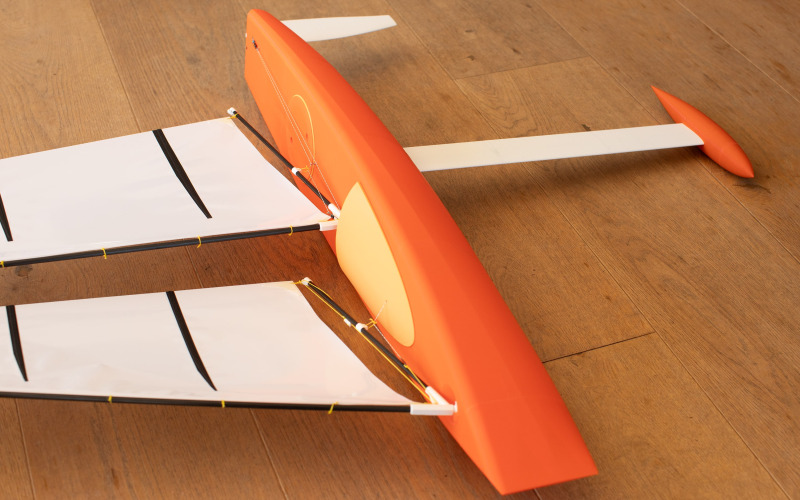
These are the instructions for building the Racing Sparrow RS-850 3D printable rc yacht. The RS-850 is really easy to build and a fast and exciting model to sail!
Contents
- 1. Overview
- 2. Preparation
- 2.1. Tools Required
- 3. 3D Printing
- 3.1. Colour Batches / Filament Choice
- 3.2. Print the Parts
- 4. Hull Build
- 4.1. Hull Preparation
- 4.2. Hull Assembly
- 4.3. Hull Cabin
- 4.4. Cut Hatch Supports
- 4.5. Sheet Exit Tube
- 5. Electrics
- 5.1. Servo Tray & Binding Receiver
- 5.2. Battery Box
- 5.3. Sail Arm Installation
- 5.4. Rudder Horn Cut & Install
- 5.5. Servo Tray Installation
- 6. Rudder & Mainsheet Installation
- 6.1. Main Sheet Routing
- 6.2. Rudder Internal Carbon
- 6.3. Rudder Push Rod
- 6.4. Rudder Pin
- 6.5. Centering & Trim
- 7. Hatch & Anchor Pin
- 7.1. MainSheet Anchor Pin
- 7.2. Hatch Plate Fixing
- 7.3. Seal Anchor Point
- 8. Keel Build
- 8.1. Keel Blanks Assembly
- 8.2. Join Bulb to Keel
- 8.3. Carbon Reinforcement
- 8.4. Bulb Filling
- 8.5. Final Keel Steps
- 9. Masts & Booms
- 9.1. Cut Mast & Boom Sections
- 9.2. Mast Disk Installation
- 9.3. Gooseneck Joiner & Boom
- 9.4. Attachment Points
- 10. Sail Making
- 10.1. Workspace Setup
- 10.2. Sail Shape Cuts
- 10.3. Sail Corners & Battens
- 10.4. Leading Edge Tape
- 10.5. Lacing Sails to Masts
- 10.6. Mainsheet Loop
- 10.7. Jib Sheet Adjuster
- 11. Main Sheet & Radio Setup
- 11.1. Main and Jib Sheeting
- 11.2. Boom Angle & Trim
- 11.3. Radio Fine Tuning
- 12. Ready to Sail
- Printing Guide
1. Overview
The RS-850-3D is a 3D printed radio controlled yacht. This is our fastest most innovative design yet! This build is suitable for ages 7 and up.
For 3D printing advice and tips read our in-depth blog post.
2. Preparation
2.1. Tools Required
These are the tools you will need to complete the build. None of these tools are mandatory, you may be able to do the job with what you have. This list makes the job easy.
- Craftknife
- Hacksaw or Dremel
- Drill
- Small plyers
- Scissors
- Hammer, a small one is great
- Small round hobby file
- Needle
- Metal Ruler
- Sandpaper
- Marker Pen
3. 3D Printing
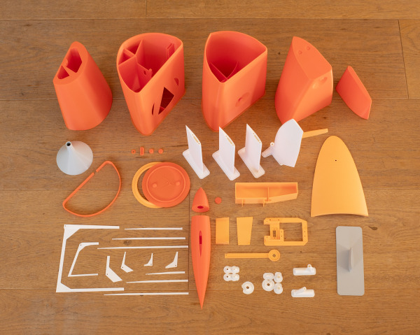
For this project the minimum printer bed size required is 200 x 200 x 200mm (xyz). This is within the capability of most small to mid size hobby 3D printers.
The Rudder and Cabin come in 2 sizes. The smaller size for each can be printed on 200mm z-axis printers. The larger cabin requires 240mm z-axis height, the larger rudder requires 223mm z-height.
The Bow Also comes in 2 configurations. You can print it as 1 part with Part E, or as a separate bow bumber setup with Parts E21 & E22.
3.1. Colour Batches / Filament Choice
Print part colours in batches, like blue hull, white keel and rudder fins.
It really helps before you start to figure out the colour combos to save you extruding and retracting more than you need to.
At RacingSparrow we use mostly PLA+ to print all the parts but have also used standard PLA, clear PLAs, silk PLAs. All of these materials are great to use. We do find that PLA+ can withstand more punishment and is a little more heat resistant than other PLA's.
3.2. Print the Parts
3d print all the parts. Use the checklist tab to see print settings for each part and keep track of progress.
4. Hull Build
4.1. Hull Preparation
-
A-RS850-Hull-Stern.stl
-
Masking Tape
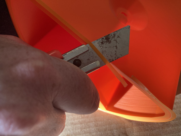
Clean up the printed parts carefully, mainly around the joins with sandpaper, craft knife, and file. Trim off the brims and check the joins for accuracy.
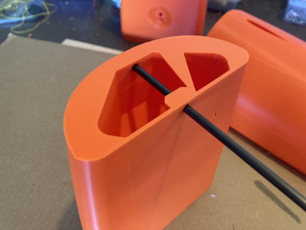
With Part A, the stern holes for the rudder and main sheet need to be clean and ubobstructed with any print artefacts. It's a lot easier to discover and fix any issues before joining the hull parts.
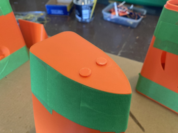
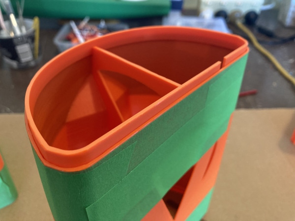
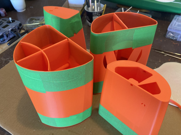
Masking Tape the hull joins on both sides of the joins so when you glue them together you don't get glue over-run at the joins.
4.2. Hull Assembly
-
A-RS850-Hull-Stern.stl
-
B-RS850-Hull-Rear-Mid.stl
-
C-RS850-Hull-Mid.stl
-
D-RS850-Hull-Foredeck.stl
-
E-RS850-Hull-Bow.stl
-
F-RS850-Bow-Join-Lug.stl
-
G-RS850-Hull-Rear-Joiner.stl
-
(CA Glue) Superglue 20g
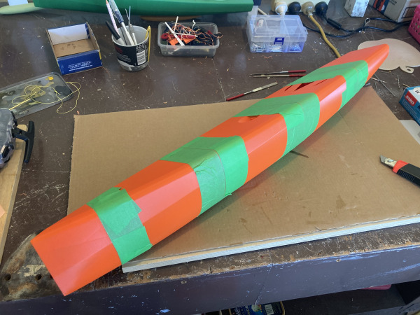
Super glue the hull together starting from the back of the boat and work forwards. Use plenty of glue to ensure the joins are water tight.
To glue the parts A&B together you will first need to glue part G - Hull Rear Joiner to part B first. This part is required because of the angle of the sides of the hull don't allow a workable print in place join so a reversed join needs to be glued in first.
For the bow there are 2 locator plugs which align the bow and foredeck parts. Sand the edges of the small plugs to get a good test fit before glueing together.
Now that the boat is now one piece and while the tape is still on the hull, run a bead of superglue along each join, then quickly wipe away the excess with a clean rag. This will seep into the gap and weld the joins together.
Remove the tape straight away before the glue sets completely.
4.3. Hull Cabin
-
H-RS850-Cabin-Large-z240.stl
-
H2-RS850-Cabin-Small-z190.stl
-
(CA Glue) Superglue 20g
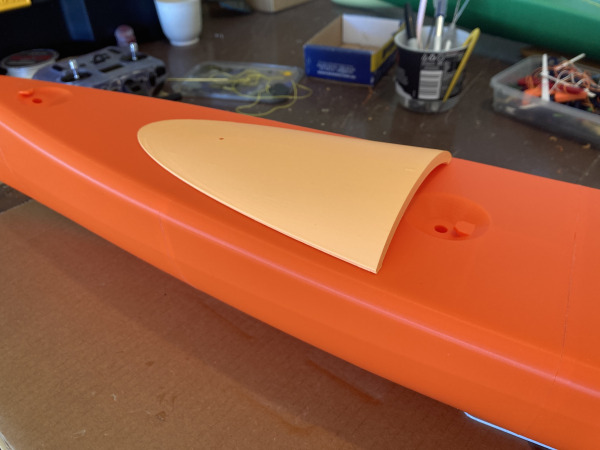
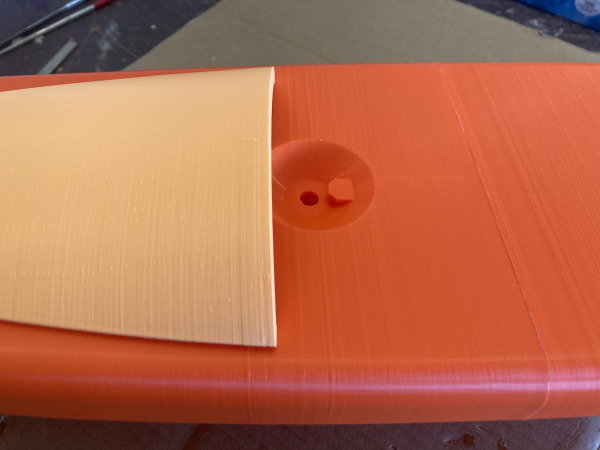
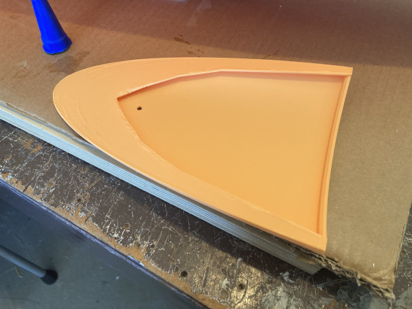
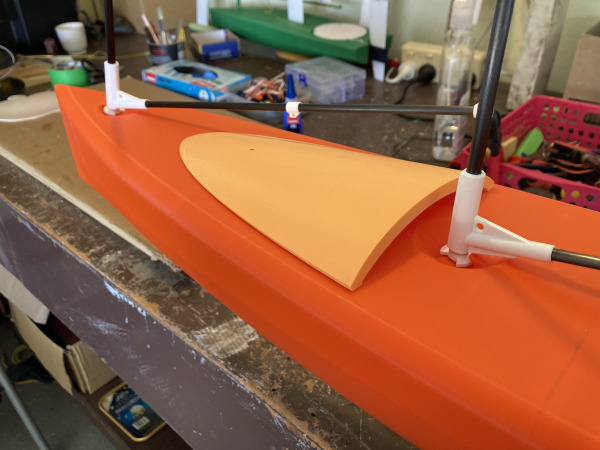
Glue the cabin onto the hull. The jib outlet hole should sit right above the front join in the hull.
To centre the cabin measure from the hull join to the back of the cabin 75mm; add some masking tape as a temporary guide mark.
The cabin should partially cover the mast recess hole.
The cabin provides some curved structural support to the hull instead of having an internal vertical beam. It is a design element that is required for strength.
4.4. Cut Hatch Supports
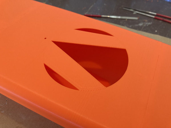
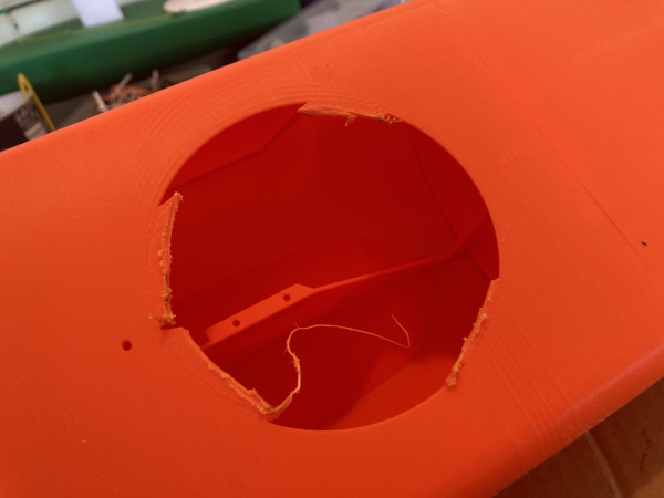
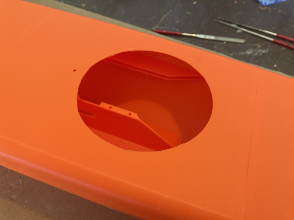
Use a dremel or a craft knife and cut off the print supports. Clean up the hull opening so it's clean and as round as you can make it. Test fit the hatch plate to make sure it sits flat on the deck.
4.5. Sheet Exit Tube
-
A-RS850-Hull-Stern.stl
-
(CA Glue) Superglue 20g
-
Masking Tape
-
Brass Tube 1/8
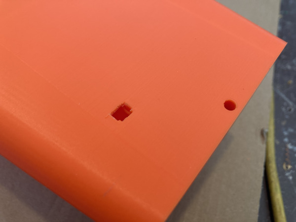
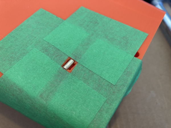
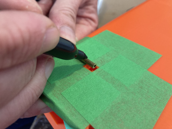
First break off the print in place support triangle covering the hole and clean up the edges with a craftknife and/or file. Mark the brass tube length against the exit hole with a marker pen.
Cut slightly oversize with a Dremel or Hacksaw then file the ends until there is a snug press fit. Glue with small drops of superglue in each seat in the PLA+.
5. Electrics
5.1. Servo Tray & Binding Receiver
-
S-RS850-Servo-Tray.stl
-
Radio Receiver
-
Rudder Servo - Emax 3054
-
Sail Servo
-
On/Off Switch
-
Battery 4AA Holder
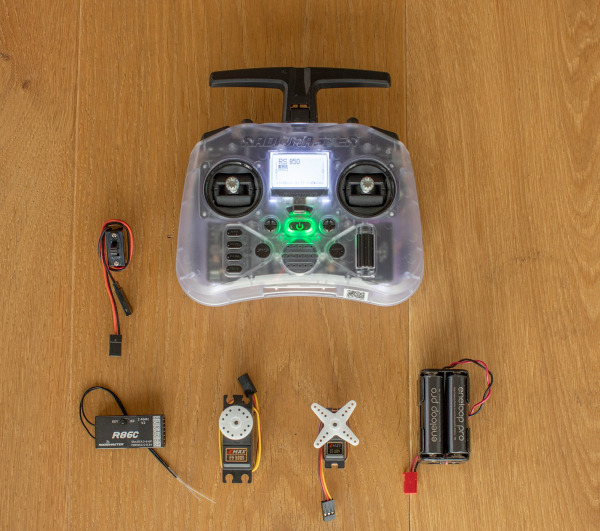
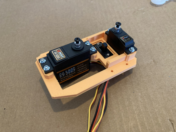
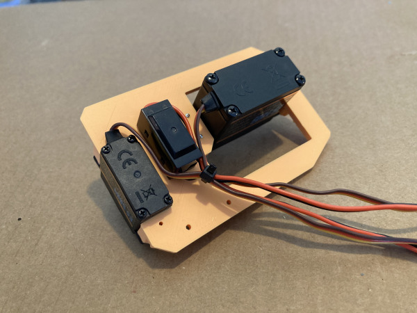
Screw in place the on/off switch.
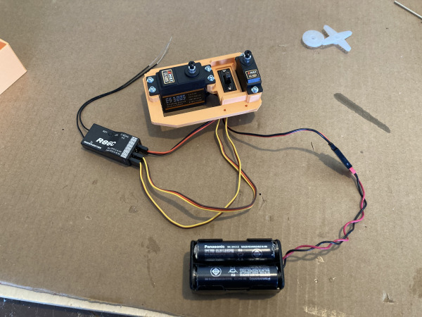
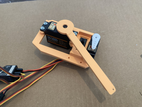
Screw servos onto the servo tray. Use just the screws the servos come with and no rubber feet or ferrules needed.
While the servos and wires are outside the boat is the best time to bind the transmitter to the receiver and program the input channels. This will be quite specific to the brand of gear you have.
To put the receiver in bind mode press the small button on the receiver and at the same time switch the on button and give the receiver power. A red light will then flash.
Search youtube and google for relevant information on how to bind and program your transmitter. I find on my RadioMaster Pocket that channel 1 is rudder and channel 3 is the sail arm by default. I plug the battery switch into channel 5 or 6.
The battery compartment fits a 4xAA square pack. I use standard rechargable NiMh batteries and a black square battery holder with JR plug. This is the cheapest when you consider the battery charger cost as well.
Note: there is a STEP file for the servo tray so you can adjust the 3d model to your specs if the servos you have are a different size. You can open a STEP file in a program like Fusion360 to re-create a new STL file.
5.2. Battery Box
-
O-RS850-Battery-Box-Bracket.stl
-
P-RS850-Battery-Box-Lid.stl
-
Q-RS850-Battery-Case.stl
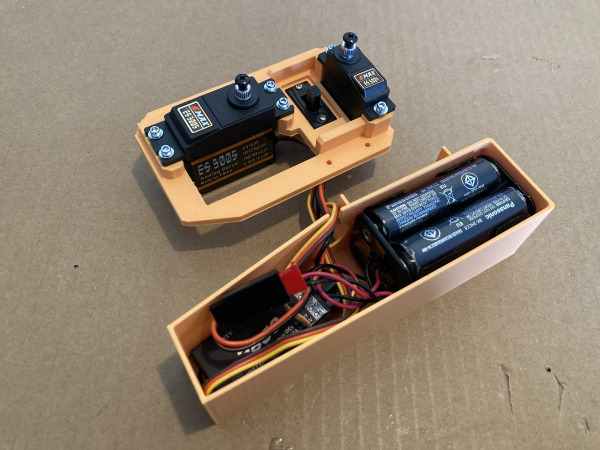
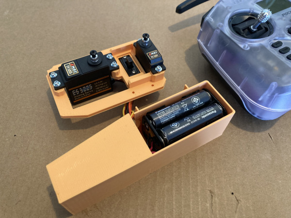
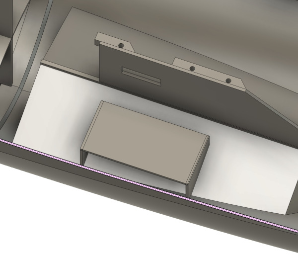
Glue the battery box lid to the battery box, then glue the battery bracket into the hull. When the bracket dries then glue the battery box into the hull. It is designed to keep the weight centralised about the keel. It needs to be as forward as possible.
5.3. Sail Arm Installation
-
R-RS850-Sail-Servo-Arm.stl
-
(CA Glue) Superglue 20g
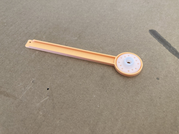
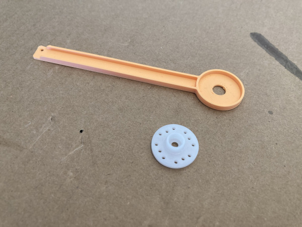
For the sail arm glue a round servo horn to the underside of the printed sail arm using superglue. It welds the two together and is very strong. Make sure to glue it centred. The top side needs to be accessible for the servo screw.
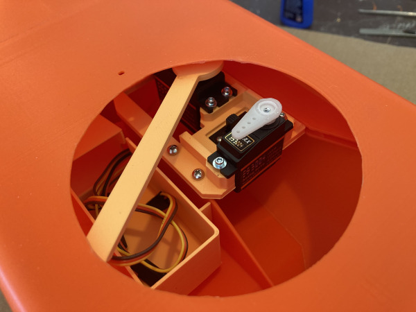
The servo should throw the arm 90 degrees giving the perfect amount of travel for the boom. When the arm is in the sail out position it should just be clear of the rudder servo mechanism by 3 or 4mm.
5.4. Rudder Horn Cut & Install
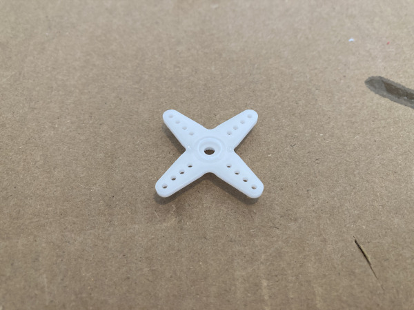
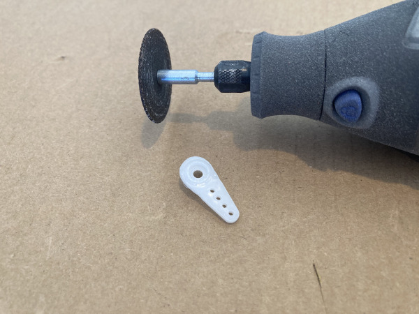
Take a standard 4 prong servo horn and chop off 3 of the prongs.
With the electrics on and the rudder centred attach the horn to the servo at 90 degrees.
5.5. Servo Tray Installation
-
Screws 3mm
Install the servo tray and route the wires into the battery box. Screw the servo tray into the hull with the two 3mm screws.
6. Rudder & Mainsheet Installation
6.1. Main Sheet Routing
-
A-RS850-Hull-Stern.stl
-
(CA Glue) Superglue 20g
-
Braid Line
-
Swivel & Clips
Direct from the spool thread your braid line through the stern hole in the boat. Let gravity do the work by standing the boat on it's bow and threading the braid carefully down through the hole. It may take a number of attempts, this is normal!
Once you see the braid inside the boat grab it with plyers or fingers and pull through some length.
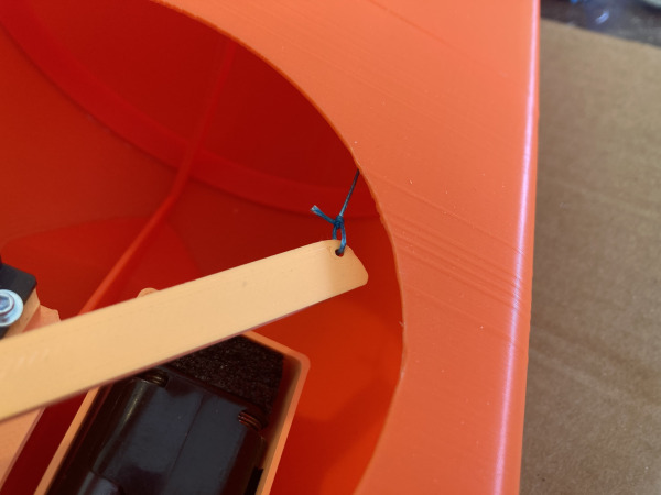
Tie the braid to the sail arm then CA glue the knot for a permanent fixture.
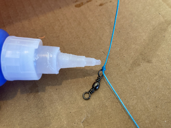
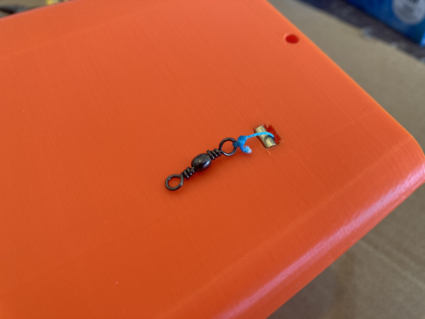
Now from out side the boat cut the braid to length then feed up through the brass exit tube and tie to a fishing swivel. When the arm is fully in-board the swivel should be 1cm away from the brass exit tube.
Once the above is CA glued you now have the main sail control line sorted and ready for a later stage in the project.
6.2. Rudder Internal Carbon
-
(CA Glue) Superglue 20g
-
Carbon Rod Round 3mm
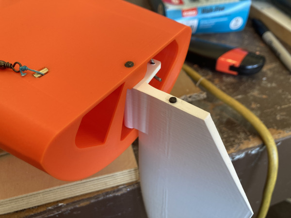
Slide a 3mm carbon rod into the rudder and with a marker measure where to cut the top. It should be flush with the top of the rudder.
Now cut then super glue in place the carbon rod. The simplest way is to coat the carbon in CA glue, quickly rest the in the top of the hole then tap in place with a hammer before the glue sets.
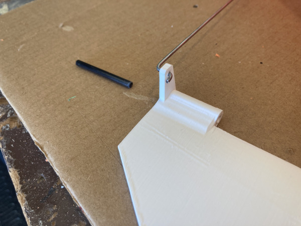
6.3. Rudder Push Rod
-
Control rod & clevis
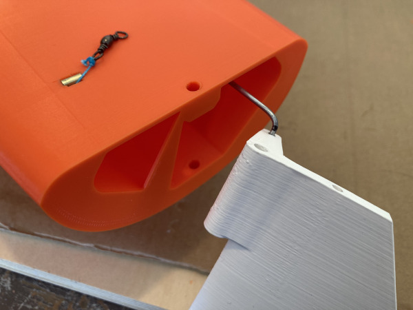
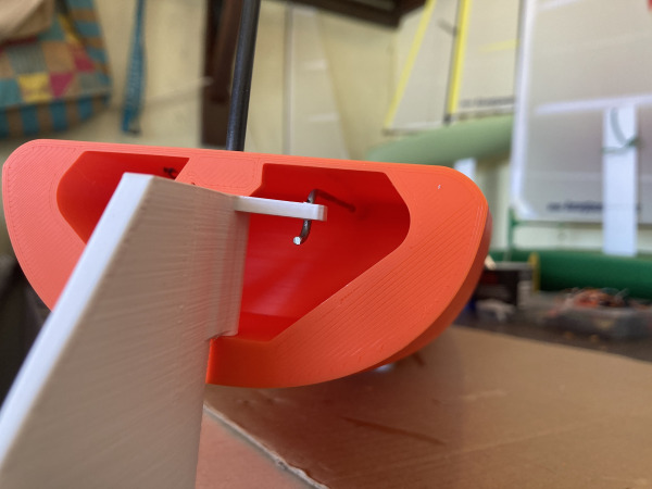
Note the measurements needed for the push rod. Bend this into shape with a pair of pliers.
The threaded part will end up attached to the servo control arm inside the boat.
For the rudder arm bend a z bend attachment point.

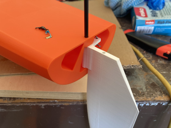
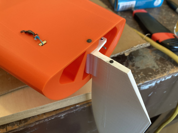
6.4. Rudder Pin
-
N-RS850-Rudder-Short-z195mm.stl
-
N2-RS850-Rudder-Long-z223mm.stl
-
Carbon Rod Round 4mm
Cut a 4mm diameter carbon rod to length of 50mm.
Now test fit this in the rudder gudgeon holes and the rudder itself. You may find you need to gently drill out the hole or file with a small round file to get a snug fit for the boat parts and a loose or movable fit for the rudder.
Once happy tap the rod into place with a small hammer. You may find a snug fit is all that is needed or you may want a small drop of super glue to keep it in place. I find a no glue approach is good for maintenance or re-use of a rudder on another boat.
6.5. Centering & Trim
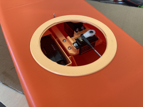
Now thread the push rod through the hull exit hole and thread onto the clevis attached to the servo.
Ideally you want the rudder as centred as possible with neutral trim on the transmitter. Turn the clevis on the thread to get the best push rod length then screw the servo arm to the servo with push rod all attached.
Now fine tune the centering with transmitter trim controls.
To have a really smooth sailing experience I program lots of expo into the rudder so that any control inputs on the rudder and very subtle to begin with and ramp up as the controls move toward their end point. You don't need a lot of rudder movement sailing upwind with the RS850, she is very balanced and will sail herself most of the time.
7. Hatch & Anchor Pin
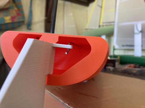
A "Split Pin" can also be known as a "Cotter Pin" in the USA.
7.1. MainSheet Anchor Pin
-
I-RS850-Pin-Anchor-Seat.stl
-
I2-RS850-Pin-Anchor-Washer.stl
-
(CA Glue) Superglue 20g
-
Masking Tape
-
Split Pin / Cotter Pin
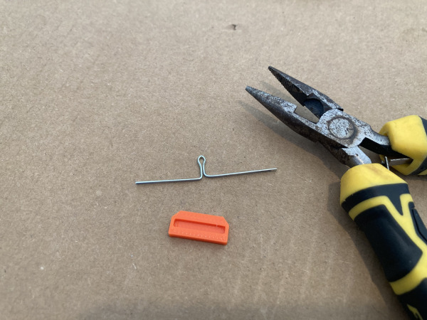
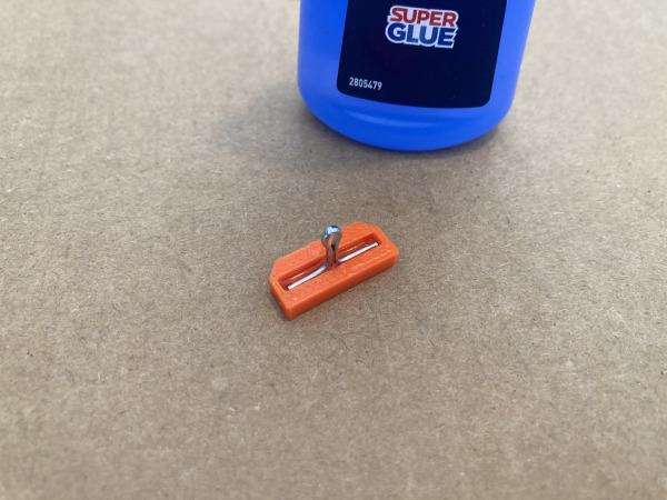
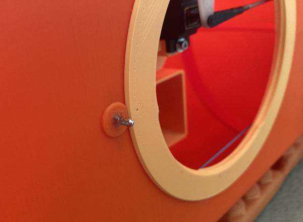
Build one sheet anchor by bending a split pin with pliers to form a T-shape. Super glue the t shaped pin into the anchor block. You may need to clip the ends of the split pin to make it fit in the slot.
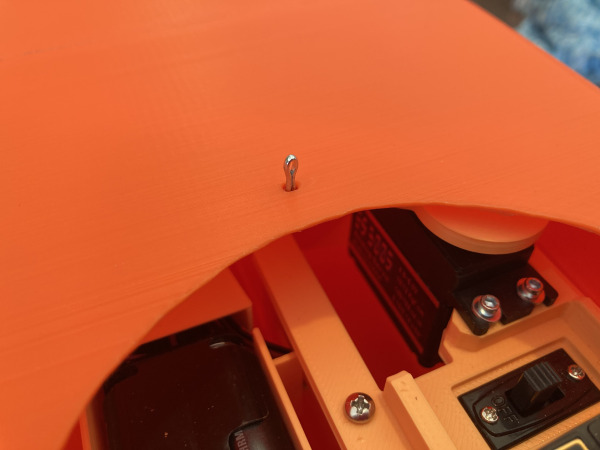
Tape around the hole on the top side of the deck to stop finger marks then glue the anchor from inside the hatch with superglue. Make the loop of the metal pin front-facing.
7.2. Hatch Plate Fixing
-
T-RS850-Hatch-Plate.stl
-
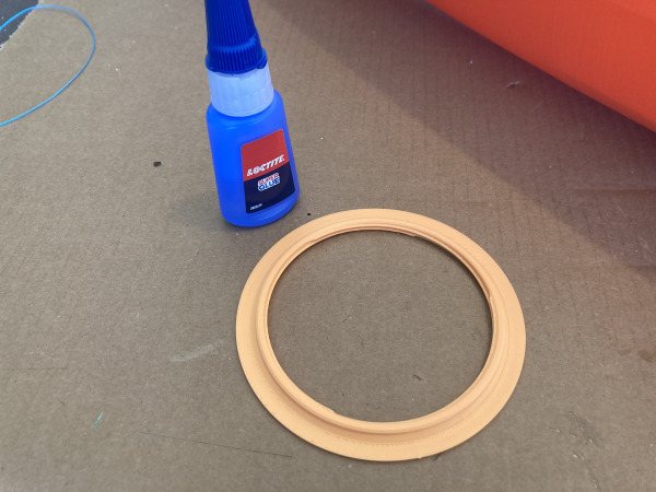
(CA Glue) Superglue 20g
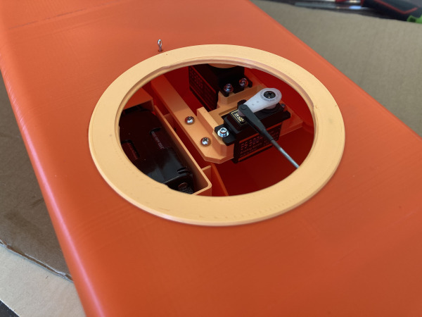
Test fit the hatch plate and ensure nothing is rubbing when the arm turns. Measure twice, glue once!
When happy apply plenty of super glue to the underside of the plate and glue it to the deck whilst applying moderate pressure for 20 seconds.
Make sure to line up the hatch sitting on the centreline of the boat with the small printed hole in the plate.
Note: the hatch lid also has a small printed hole, which is the starting point for closing the hatch. Line up the two dots then twist clock-wise firmly to close.
7.3. Seal Anchor Point
-
Epoxy Resin
For the printed washer, you may need to trim an edge with plyer-cutters or craftknife to get it to sit snugly up against the hatch plate.
Mix a small amount of epoxy or araldyte and seal the mainsheet anchor gaps so no water can enter the hull.
Next pop the printed washer over the pin to finish a tidy and water proof fitting.
8. Keel Build
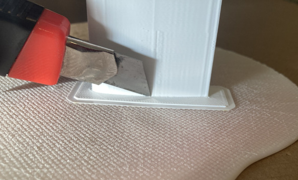
Trim the keel blanks in preparation for the next steps.
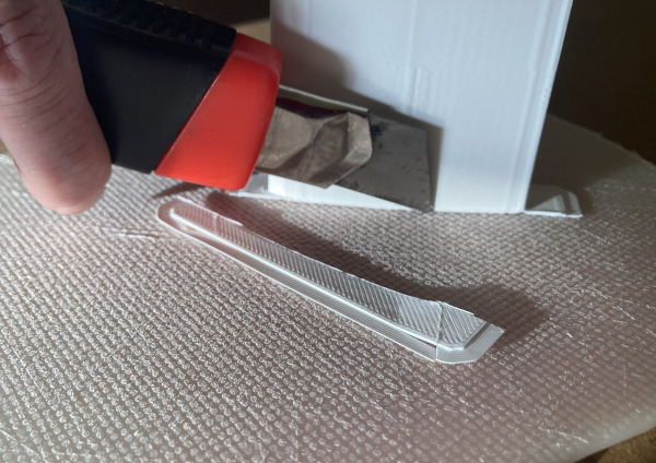
8.1. Keel Blanks Assembly
-
M-RS850-Keel-Section.stl
-
(CA Glue) Superglue 20g
-
Masking Tape
-
Carbon Rod Round 3mm
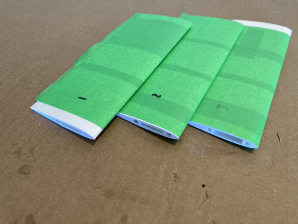
Using masking tape cover the keel completely with tape to stop glues and hand marks while you build. Make sure you leave the ends clear of tape so it can glue into the bulb slot and into the hull.
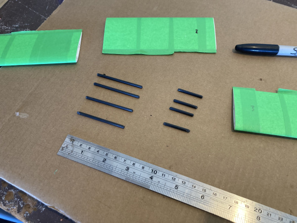
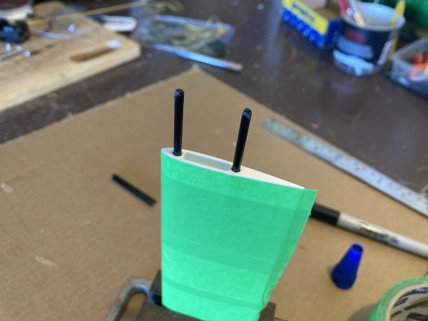
The keel blank has 30mm deep holes in both ends. The end result should be a 3 piece joined keel blank with carbon reinforcements 3mm rods at both ends to create a strong keel with little to no air inside.
Cut 4xlengths of 3mm Carbon rod to 60mm in length for the inside joins and 4x30mm for the end holes. Clean up the ends of the carbon with sandpaper. Super glue the 3 keel blanks together with the carbon rods.
8.2. Join Bulb to Keel
-
J-RS850-Bulb-Main.stl
-
(CA Glue) Superglue 20g
-
Masking Tape
Prepare the keel to fit neatly into the bulb trench and also prep the other end to fit into the hull. It's much simpler to do both ends before the bulb is attached. When both ends fit correctly then super glue in place the bulb to the bottom of the keel.
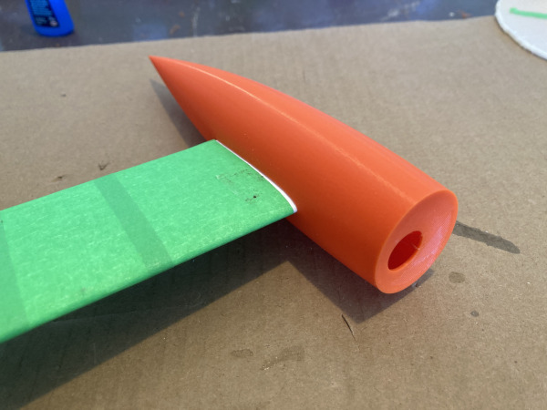
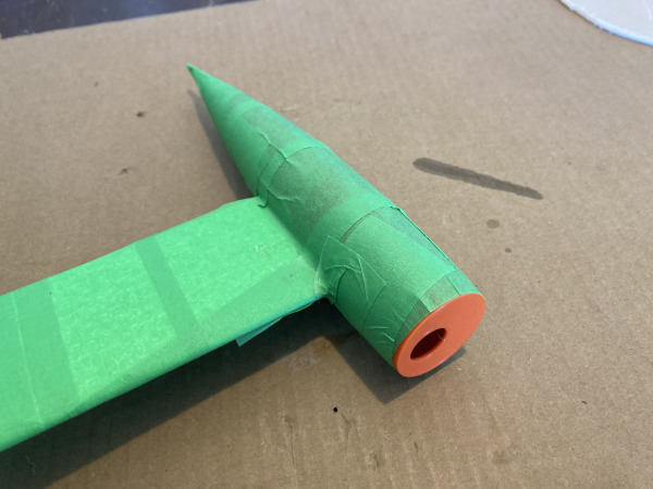
8.3. Carbon Reinforcement
-
Epoxy Resin
-
Carbon Square Rod 4mm
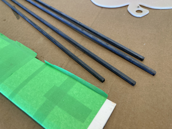
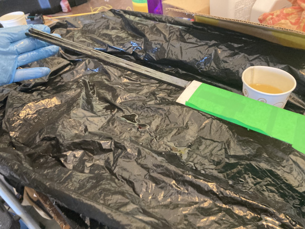
Sand the carbon square 4mm rods so the shiny surface is roughed up. I do this quickly with the dremel. This helps the resin bind to the fibres of the rods.
Prepare an area for gluing the carbon square 4mm rods into the keel. An old scrap of cardboard box is an ideal way to do this. This is going to get messy. Wearing gloves mix some epoxy resin. You need to mix enough to completely coat all 4 rods on all sides.
Do this with your hands whilst wearing the gloves. Slide the 4 rods into the keel trench so they go all the way to the bottom; right through to the base of the bulb. You may need to tap them in place with a hammer.
I find it a useful to switch to a fresh set of gloves part way through so you don’t cover your tools in glue. Leave the keel sitting upright whilst drying to prevent unwanted bend.
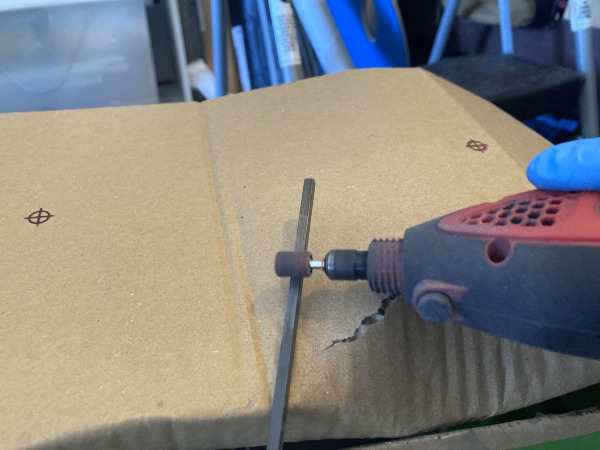
8.4. Bulb Filling
-
J-RS850-Bulb-Main.stl
-
K-RS850-Bulb-Nose.stl
-
Epoxy Resin
-
Lead Shot 900g
-
Methylated Spirits / Denatured Alcohol
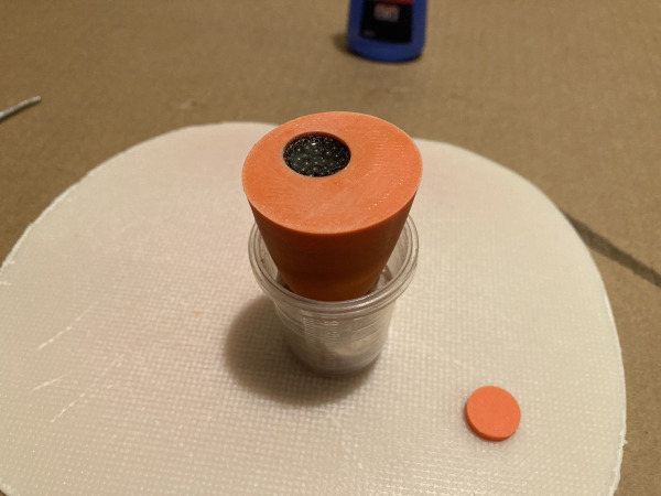
Place keel in a vice so the bulb is upright and the pour hole is at the top. Place the nose in a small plastic cup with some packing to hold it upright.
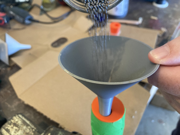
Fill the two bulb parts with lead shot leaving a gap for the glue pouring. Use the printed funnel to assist in the pouring of the both the lead and the resin. Note that the bulb actually has only 905g of lead shot inside. The rest of the weight is made up by the carbon rod, the PLA+ shell and the resin filling.
Prep the area for resin drips, cardboard underneath and a rag to mop up an drips or excess resin. A change of gloves part way through can be a good idea.
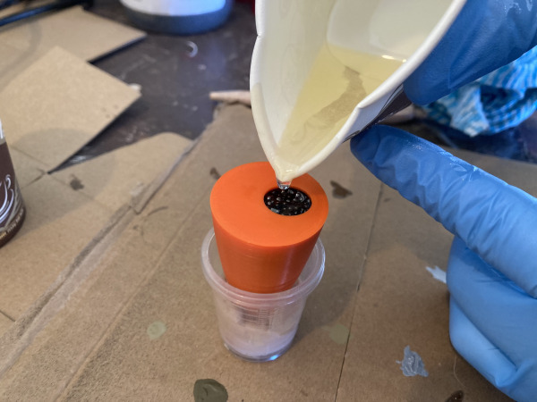
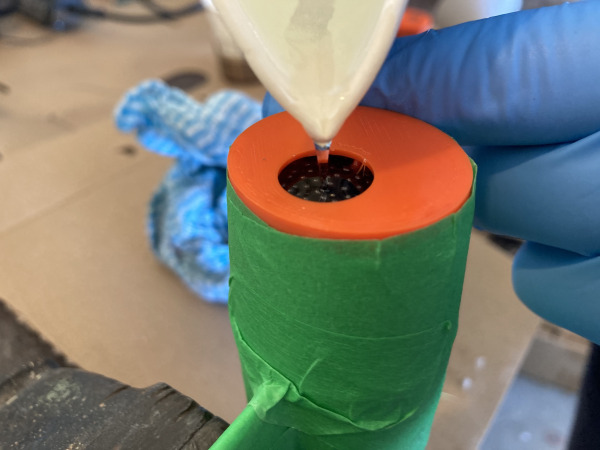
Mix approximately 100ml resin thoroughly, then add 15ml mineral turpentine and mix again. Now slowly pour resin in via the funnel allowing it to soak through lead shot. It's a slow process that requires some patience. You can also pour direct from a pinched cup. I tend to start with the funnel then switch to just using the cup to finish off.
Tap the bulb with a hammer to release any air bubbles. Top up with lead and resin so that it goes all the way to top.
Leave this to sit for around 12 hours or until completely set.
8.5. Final Keel Steps
-
L-RS850-Bulb-Joiner-Lug.stl
-
(CA Glue) Superglue 20g
-
Epoxy Resin
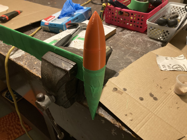
Once the bulb has set super glue the bulb nose to the main bulb using the round joiner lug in the whole to key the two parts in place. Ideally you want no air inside the bulb. You may want to fill any voids with extra resin or filler/putty.
Cut the excess square carbon inners off and flatten the top of the keel.
You should now have a complete keel and bulb.
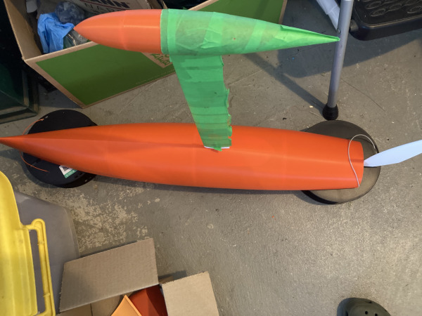
Now epoxy the keel into the hull.
Now set the boat aside sitting upside down and let the keel set in place for at least 12hrs.
9. Masts & Booms
9.1. Cut Mast & Boom Sections
-
Carbon Tube 5mm
-
Carbon Tube 6mm
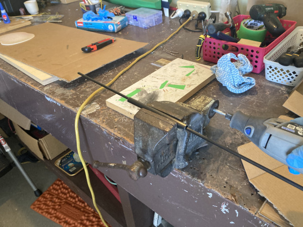
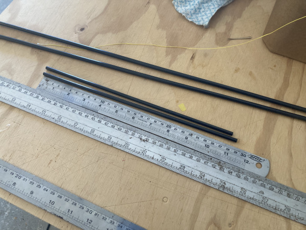
Cut the (6mm mast x 2) and (5mm boom x 2 ) to the plan dimensions found in the sail plans tab (Second Image).
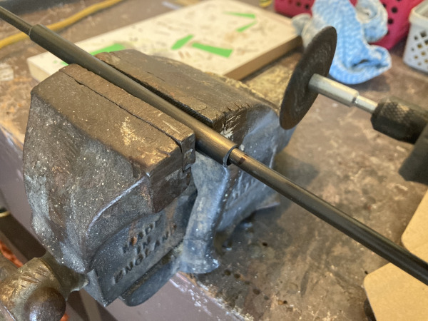
A cool trick for cutting carbon is to pop an off-cut piece of tube in the vice to use as a holder.
The RS850 has only 1 sail plan. We found it can be sailing in low to very high winds with this one set of sails.
You could make a higher wind set of sails by reducing the main mast to the same height as the jib sail. Using the same jib for both rigs will work well.
9.2. Mast Disk Installation
-
X-RS850-Universal-Mast-Disk.stl
-
Carbon Tube 6mm
-
(CA Glue) Superglue 20g
For both masts follow the same instructions that follow.
Slide the joiner up the mast and out of the way in preparation for the next part.
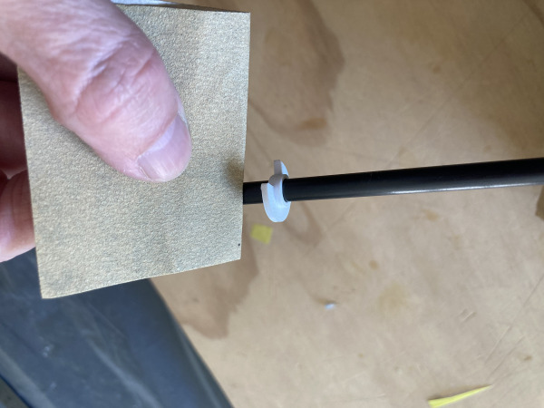
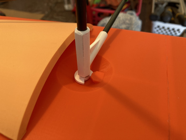
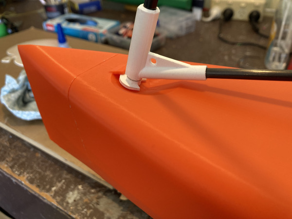
Insert the mast into hull, position the disk so the mast spins freely but cannot lift out. Gently sand where the disk will sit in the mast and then re-position.
Once happy with the disk placement gently remove the mast from the hull and glue the disk by running superglue around the top and bottom. The glue will seep into the gaps and bond it.
Wipe away any excess glue and let the glue dry.
9.3. Gooseneck Joiner & Boom
-
V-RS850-Main-Goose-Neck.stl
-
W-RS850-Jib-Goose-Neck.stl
-
Carbon Tube 5mm
-
(CA Glue) Superglue 20g
For both masts follow the same instructions that follow.
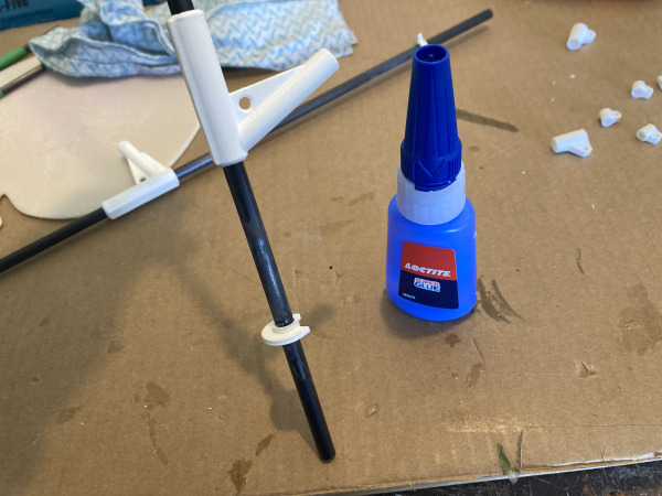
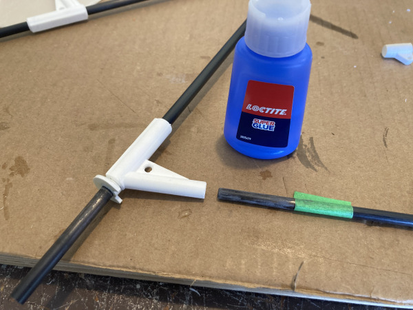
Add plenty of glue to where the joiner will sit and quickly slide the joiner in place before the superglue takes hold. You only get one chance so practice first and prep well. Measure twice, glue once!
The main mast disk needs to prevent the mast popping out when the boom is just past 90 degrees. The jib boom will be completely facing the wrong way when the mast can pop out. (re-write this part).
Lightly sand the boom end and glue the carbon boom into the joiner.
9.4. Attachment Points
-
Y-RS850-Mast-Topper.stl
-
Z-RS850-Boom-Attachments-x-2.stl
-
(CA Glue) Superglue 20g
For both masts follow the same instructions that follow.
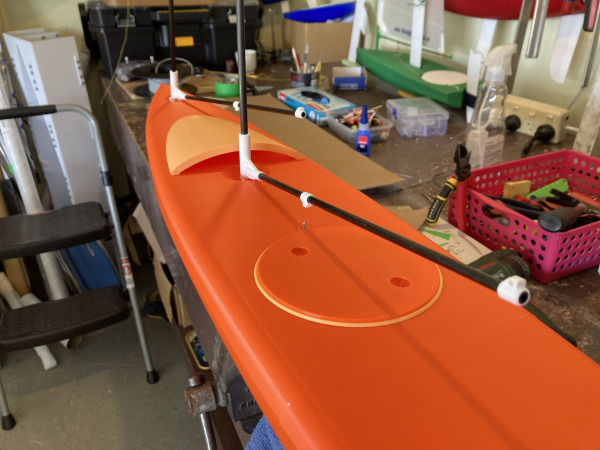
Position and glue the boom attachment points as per the sail plans. One for the end of the boom and the other for mainsheet loop.
Glue the topper attachment making sure it is aligned with the boom.
10. Sail Making
10.1. Workspace Setup
Use a flat, cuttable surface such as scrap vinyl, plywood or cardboard.
10.2. Sail Shape Cuts
-
Sail Material
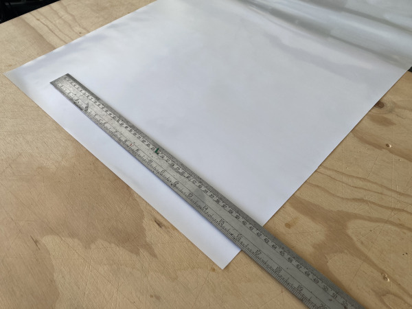
Each sail is ideally made from one piece of material. No seams are needed unless your material you are using comes in smaller pieces like A4 architectural drafting film.
You can use many things for sail material. Drafting film, reflective grow mylar, ripstop nylon, spinnaker sail offcuts, floral mylar. If you need to; first join panels of material to form one large rectangle as per the sail plans.
Cut the sail rectangles from your one piece material using the plan dimensions that are in the sail plans tab on this page.
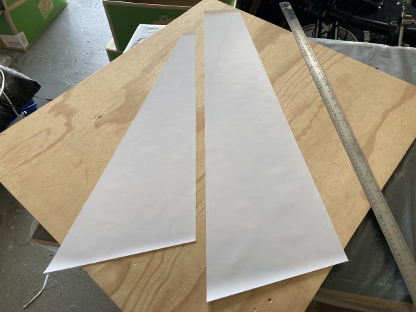
Measure, mark then cut the mast and boom offsets according to the sail plans.
You might think the measurements seem incorrect and the sails too short for the carbon mast and boom shapes. Once rigged up the mast and booms will bend and close the gaps. This tensions the trailing edges of the sails so they are firm. This is really important for the sails to have maximum power. The sail designs went through many rounds of refinement to arrive at these optimal geometries.
Measure, mark then cut the square top measurement down to the bottom corner to complete the final outer shape of both sails.
10.3. Sail Corners & Battens
-
Z3-RS850-Sail-Battens.stl
-
Spinnaker Repair Tape
For both sails do the following:
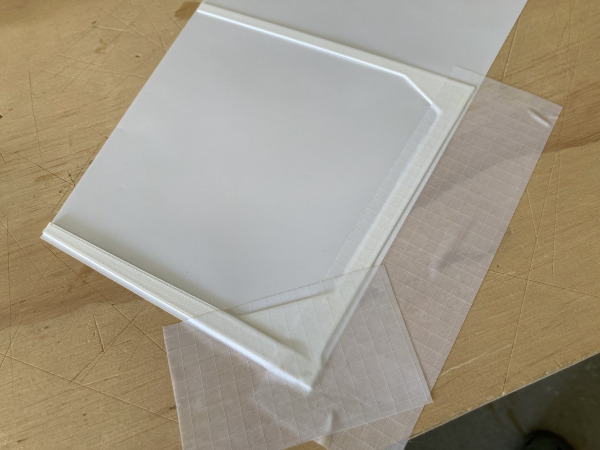
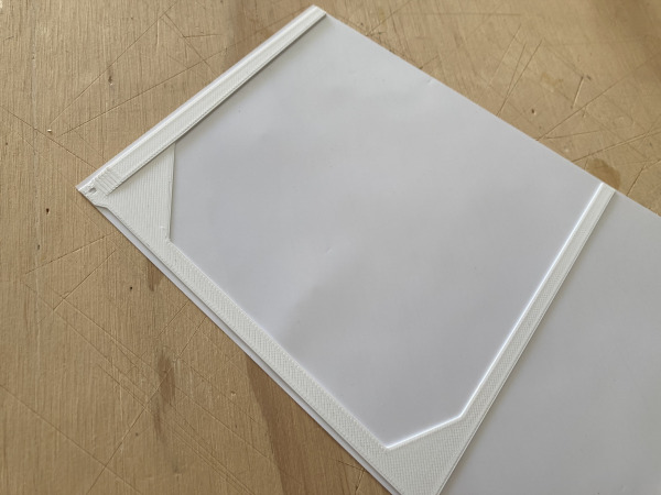
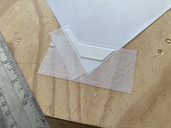
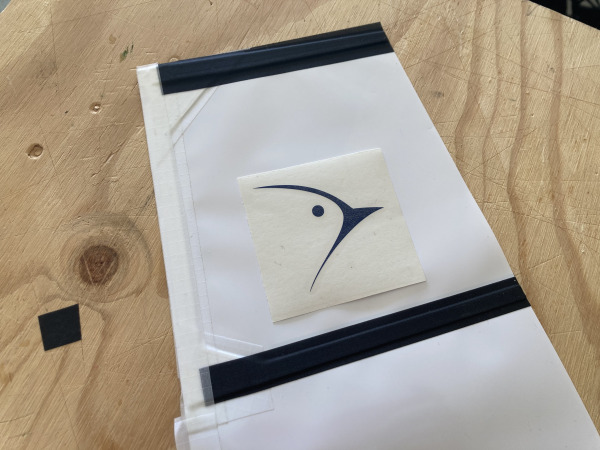
Tape the 3D printed corners in place using spinnaker tape. The tape should go well past the sail edges. The printed parts will be taped to one side of the sail but put tape on both sides so the tension of the tape is matching one side to the other. This will prevent bowing or mis-forming.
Next trim the tape edges off with a craftknife.
Install the sail battens using tape strips. Find placement measurements on the sail plans for the battens. Do the same as the corners and tape both sides to prevent warping.
10.4. Leading Edge Tape
-
Spinnaker Repair Tape
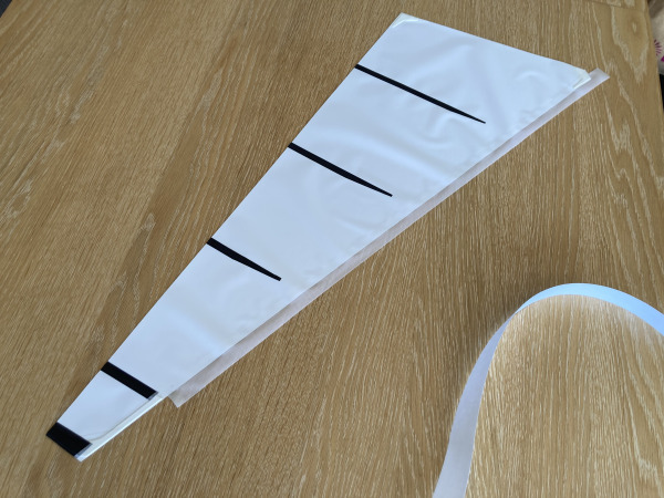
For both sails apply sail tape to both sides of the leading edge stretching the sail while taping.
For this step it really helps if someone helps you to stretch the sail as you apply the tape. This will reduce any unwanted wrinkles.
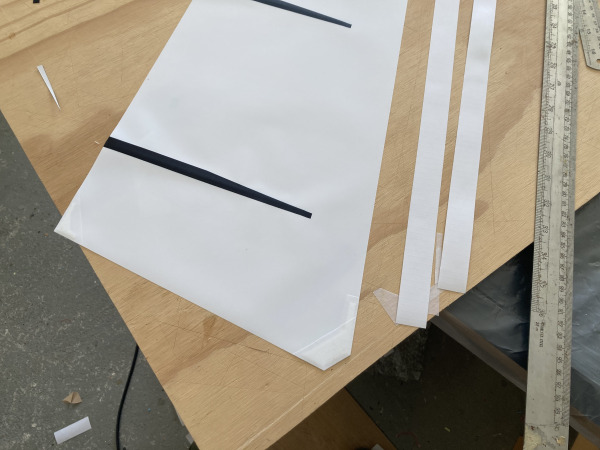
Trim the tape to leave a 5mm double thickness leading edge and flush edges.
At the top of the sail cut a notch in the tape down to the second square batten. That part gets in the way of the mast and disturbs the sail shape. Look at the images closely to see what I mean.
10.5. Lacing Sails to Masts
-
(CA Glue) Superglue 20g
-
Braid Line
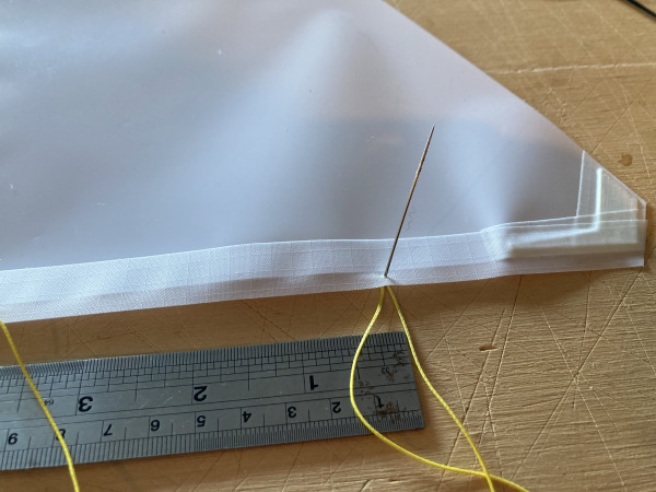
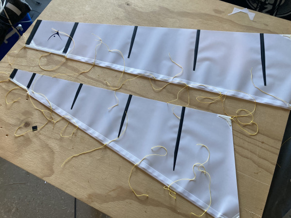
For both sails: starting at the top of the sail stitch the sail with a needle loaded with braid line. Instead of threading each loop and attachment point one at a time, it’s much easier to do this with one continuous length of braid meaning you only need to thread the needle with braid once.
Start at the top through the eyelet then every 100mm pop the needle through the leading edge sail tape. Work your way down the sail. Once down to the sail tack move across to the clew. As you do this you will need to keep threading more braid through the existing holes you have made.
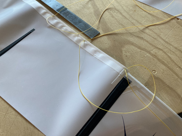
Now that you’ve got thread running through all holes you can remove the needle from the thread and starting at the top cut the braid into 200mm lengths.
Now tie each loop with a simple reef knot attaching a small loop to the sail with 2 x 100mm tails.
Again starting at the top of the sail, tie the top line to the mast topper making it snug and as close to the hole as you can. Then working down the mast tie each loop around the mast and loosely tie each attachment point. You don’t want them to be tight against the mast. You want them slightly loose so they can freely move around the mast and the sail will naturally form the correct shape governed by the sail battens.
When you get down to the tack you want to tie this so the front luff of the sail holds some tension.
For the clew it will attach to the boom end point. The sail should be slightly longer than the boom giving the sail some naturally baggy-ness that creates the aerofoil shape you want.
After this step superglue all the knots with a small dot of superglue. This will make the knots permanent and is a great trick to reduce breakages whilst sailing. Once the glue has set trim all knot ends close to the knot with a sharp craft knife.
When this step is complete you should notice both the mast and boom have slight bends in them which tensions the sails. The bend is great as it keep the sail tight and in the correct shape.
10.6. Mainsheet Loop
-
(CA Glue) Superglue 20g
-
Braid Line
For both sails:
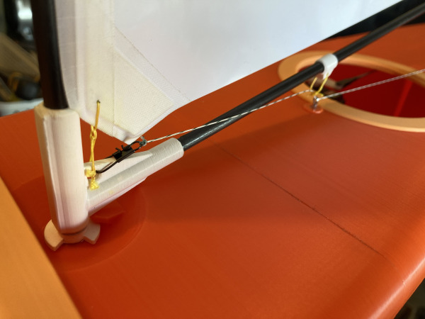
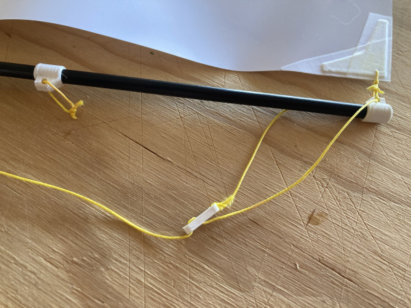
Add a mainsheet loop to boom attachments. This is used to thread the mainsheet through. The end of the mainsheet then clips to the front of the sail and keeps the lines free from tangles.
The loop needs enough room so you can easily pop a clip through just before sailing. It does not need to be tight or keep the mainsheet too close to the boom.
Tie your knot then seal with a drop of superglue. It's quite critical that this knot does not come undone!
10.7. Jib Sheet Adjuster
-
Z2-RS850-Bowsie.stl
-
(CA Glue) Superglue 20g
-
Braid Line
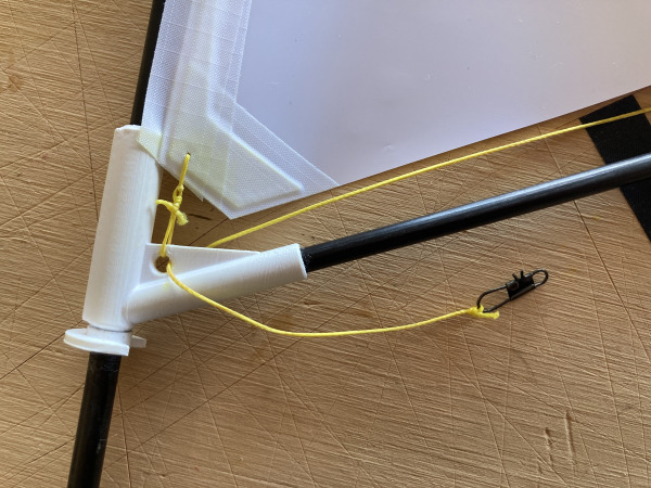
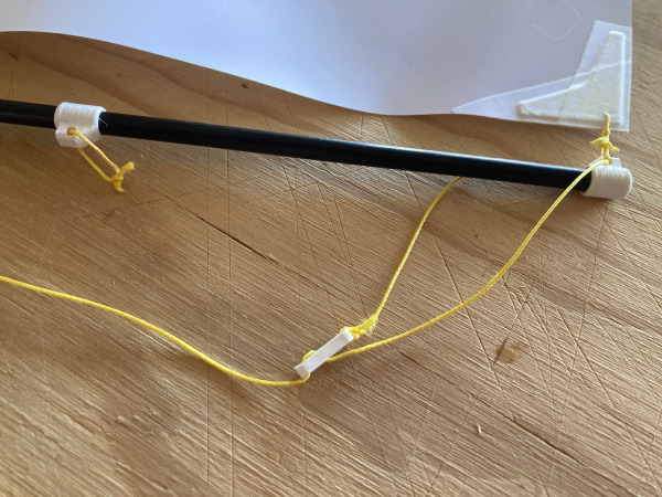
To adjust the jib sheet for different sailing conditions we need an bowsie adjuster.
It's behaves much like a tent guy rope. Use a needle to thread the braid through the printed bowsie adjusters three holes.
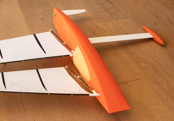
See the picture here to see how this is rigged up.
When sailing it's best to start with the jib further out than you think and slowly bring it in-board to get a feel for how it effects the power in the sails. This is mostly for sailing upwind when the wind is flowing around and betweem the jib and main sails.
11. Main Sheet & Radio Setup
11.1. Main and Jib Sheeting
-
(CA Glue) Superglue 20g
-
Braid Line
Turn on your electrics and pull the sail arm all the way inboard.
We are going to now split the mainsheet into two lines from the swivel. One for the main sheet, the other for the jib.
The main sheet line ties to the swivel - through the main anchor - through the boom loop then onto a fishing clip attached to the gooseneck. Get this as tight as you can with the boom as close to the centreline as possible. It won't be exactly in the centre, there is always some slack. This slightly off centre boom angle is perfect. I find I don't need a main sheet adjuster as you always simply want this sheeted right in and no separate tuning is ever needed.
The jib is set differently. It needs to be adjusted for the wind you are sailing in. The previous section showed you how to make the jib sheet adjuster.
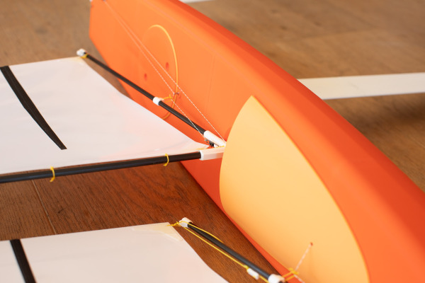
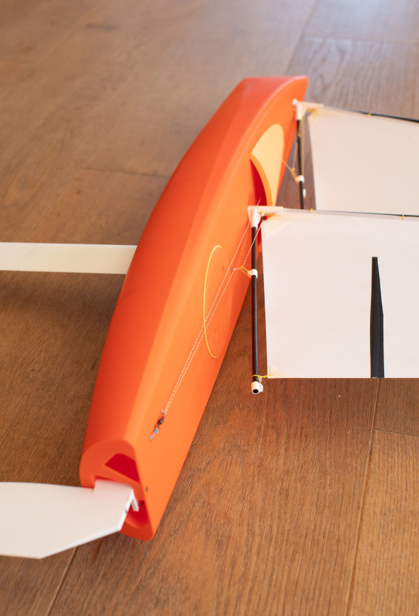
Run the jib sheet from the swivel, past the mast on the left then through the cabin hole. Now run the braid through the boom loop then tie to a fishing clip. The clip attaches to the adjuster. The photos should help to understand more about how this works.
11.2. Boom Angle & Trim
For the correct tuning of the RS850 it's very simple. The mast rake can't be altered as the mast just pop into their slots. The only thing left to tune is the mainsheet boom and jib angles.
The main boom when sailing upwind should be as close to the centreline as you can get it. I find the end of the boom to be 1-2cm from centre.
The jib boom needs further outboard. The end of the jib boom should sit just inside the edge of the hull. You some air to flow between the gap between the two sails.
Start with the suggested jib/main gap and tube whilst sailing to get the best performance from the boat. You will find in stronger winds the gap needs to be 1cm wider than light winds.
11.3. Radio Fine Tuning
Fine tune the sail trim via the transmitter trim buttons. You should only need a little bit of trim ideally.
Another excellent improvement to the handling of your boat is to add exponential to the rudder for fine control and reduced drag. Adding expo means the rudder makes more subtle movements. The RS-850 is very well balanced by design and does not need large rudder corrections when sailing in straight lines.
Remember every time the rudder is corrected it acts as a break and slows you down. Minimising rudder movement is key to sailing faster!
12. Ready to Sail
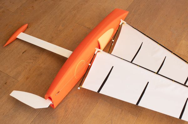
The boat is now ready to sail.
On the first sail, run the boat for about 30 seconds, return to shore, and inspect inside. You may need to add a little superglue to any joins or gaps you missed if you spy a leak.
When sailing, take a sponge, spare braid, and superglue. Be gentle on your first outing!
When built correctly, the boat remains very dry inside. The internal layout also lifts the electrics above any water, keeping the battery and receiver protected in their own compartment if water did get inside.
Well done and good luck sailing!
Printing Guide
The Racing Sparrow 3D boats are designed to be printed from PLA+. One roll of filament should be enough to print the hull parts, keel, bulb, rudder, and rig parts. The 3d model has been designed so that no part is too large making this easily printable on most home 3d printers. Minimum Printer Bed Size Required: 200×200×200mm (XYZ).
Simply load the STL files into the slicer software and start printing. All parts are pre-oriented correctly so you should not need to rotate.
For 3D printing advice and tips read our in-depth blog post.
The settings the author used on a Creality K1 Max Printer were:
PLA+ eSun
Nozzle 0.4,
Wall count of 2: top 4, bottom 4 layers
Use mouse ear for problematic lifting edges
210°C Nozzle
60°C Bed
34°C Enclosure
Either 18% infill or 100% depending on the part
300mm/s speed
Carbon Fibre
Before gluing any carbon it’s best to sand off the glossy outer coating of the spar. These coatings are just thin layers added to the carbon by manufacturers. When gluing this will add much better bond of carbon and PLA+. It’s easiest to sand these with a dremel or it can be done by hand with sand paper. Wear gloves to avoid itchy hands from the cut carbon particles. Carbon glues well with both CA and epoxy glues.