RS-RG65 Build Guide
v1.7
Recommended PLA+ Filament
These are the instructions for building the Racing Sparrow RG65 3D printable rc yacht. The boat comes with options to build two different rig styles. Una (Single Sail) & Standard 2 Sail Setup.
Contents
- 1. Overview
- 2. Preparation
- 2.1. Tools Required
- 3. 3D Printing
- 3.1. Filament Choice
- 3.2. Print the Parts
- 4. Hull Build
- 4.1. Hull Preparation
- 4.2. Anchor Points
- 4.3. Hull Assembly
- 4.4. Hatch Opening
- 4.5. Sheet Exit Tube
- 4.6. Servo Bracket & Bracing
- 5. Electrics
- 5.1. Servo Tray & Binding Receiver
- 5.2. Battery Box
- 5.3. Servo Tray Installation
- 5.4. Sail Arm Installation
- 5.5. Hatch Plate
- 5.6. Seal the Anchor Disks
- 6. Rudder & Mainsheet Installation
- 6.1. Main Sheet Routing
- 6.2. Rudder Build
- 6.3. Rudder Control Rod
- 6.4. Rudder Setup & Centering
- 7. Keel Build
- 7.1. Keel Halves Assembly
- 7.2. Join Bulb to Keel
- 7.3. Carbon Reinforcement
- 7.4. Bulb Filling
- 7.5. Final Keel Steps
- 8. Standard Rig (Main & Jib)
- 8.1. Mast Step
- 8.2. Cut Mast & Boom Sections
- 8.3. Mast Fittings & Spreaders
- 8.4. Gooseneck Installation
- 8.5. Boom Attachments
- 8.6. Rigging Wires
- 8.7. Tension Stays
- 9. Una Rig (Single Sail)
- 9.1. Cut Mast & Boom Sections
- 9.2. Mast Disk Installation
- 9.3. Spar Joiner & Boom
- 9.4. Mast Topper
- 9.5. Boom Attachments
- 10. Standard Sails
- 10.1. Workspace Setup
- 10.2. Main Sail Cutting
- 10.3. Jib Cutting
- 10.4. Corners & Battens
- 10.5. Leading Edge Tape
- 10.6. Lacing & Attachment
- 11. Una Sail
- 11.1. Sail Cutting
- 11.2. Attachment Points
- 11.3. Attach Battens
- 11.4. Attachment to Mast
- 12. Main Sheet & Radio Setup
- 12.1. Sheet Routing
- 12.2. Boom Angle - Standard/Una & Jib Trim
- 12.3. Radio Fine Tuning
- 13. Ready to Sail
- Printing Guide
1. Overview
The file set comes with many options. Bulb weights, 470g, 508g, 550g. Keel length, short, standard, long. Rudder size, small, medium, large. Keel fore/aft position.
You can build the boat with either a Una rig or Standard Rig.
Standard Rig Setup
The two sail rig is a traditional two sail rig with a deck stepped mast held in place with wire stays. The boom rotates with a printed gooseneck fitting. It's more complex to build than the Una rig but generates more power. The extra power comes from the slot between the two sails which increases the pressure differences which is what creates the drive the sail produce.
Recommended Combination
- Standard B-Rig
- 508g Bulb
- Medium Rudder
- Origin position keel
- Standard Length Keel
Una Rig Setup
The Una rig design is perfect for someone wanting a simple build. There are no stay attachment points needed in the hull and the rig is very simple to build yourself.
The Una Rig is designed to be as simple as possible using a 1 piece sail, carbon tubes and printable joiners for the tubes.
Recommended Combination
- Una A-Rig
- 508g Bulb
- Large Rudder
- -7mm offset position keel
- Standard Length Keel
Bulb Sizes
The bulb comes with STL files for 3 different bulb weights: 550g, 508g, 470g. We recommend the 508g bulb with standard keel length for our preferred combo. If you are really counting grams and want optimal light wind performance try the 470g bulb, it’s touchy to sail upwind but has great acceleration down wind.
The keel profile is an accurate NACA 12.3% aerofoil. The internal structure is designed around 4mm carbon square rod. The keel is printed in two parts. The two parts are 164mm & 146mm in length. The recommended combo is one of each of these parts R & S. You could lengthen the keel by 18mm by using (part-S x 2) The keel position fore and aft can be located in 2 positions by using hull part D or part D2. The difference is 7mm. The designer prefers the upwind performance of part D, placing the keel and weight of the bulb further forward. If you prefer better downwind performance go for the -7mm part D2.
Rudder Sizes
The rudder comes in 3 STL sizes. We recommend the large rudder for newcomers as it provides more control. The medium rudder is the designers preference while the small rudder is great for experimentation.
Servo Arrangement
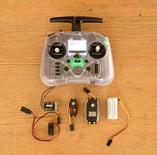
For servos the designer used with great success two cheap servos that are readily available globally: Sail Arm: Futaba S3003 Standard Size Rudder: EMAX ES3054 Mini Servo The electrics for this boat are designed to be as cheap and as simple as possible. The electrics are the heaviest part of the boat and the placement has been designed to sit central in the boat and as low as practically possible. A servo bracket is glued into the hull that also acts as a semi bulkhead for the keel trunk. This bracket is a 2 part component which includes a top tab bar. The servos get mounted on a printed plate outside the boat and installed as one unit into the hull. The plate is secured to the bracket with two screws which are easily accessible through the round hatch hole. The entire electrics assembly can be unscrewed and removed from the boat very easily with this system.
Receiver & Batteries
The receiver and cables get tucked into the front compartment of the battery box which is a simple open design. The battery compartment is designed to fit (4 x AA) batteries in a standard battery holder or any other smaller battery type. The designer recommends a (4 x AAA) battery pack with some simple foam packing beside and in front of the battery. This is a simple no frills way to have easily accessible batteries but have them snugly sitting in a compartment that is resistant to any water that may find its way into the hull.
The electrics are easiliy transferable to another build, you could build both boats with one set of electrics.
2. Preparation
2.1. Tools Required
These are the tools you will need to complete the build. None of these tools are mandatory, you may be able to do the job with what you have. This list makes the job easy.
- Craftknife
- Hacksaw or Dremel
- Drill
- Small pliers
- Scissors
- Hammer, a small one is great
- Small round hobby file
- Needle
- Metal Ruler
- Sandpaper
- Marker Pen
3. 3D Printing
3.1. Filament Choice
Print part colours in batches, like blue hull, white keel and rudder fins.
It really helps before you start to figure out the colour combos to save you extruding and retracting more than you need to.
At RacingSparrow we use mostly PLA+ to print all the parts but have also used standard PLA, clear PLAs, silk PLAs. All of these materials are great to use. We do find that PLA+ can withstand more punishment and is a little more heat resistant than other PLA's.
3.2. Print the Parts
3d print all the parts. Use the checklist tab to see print settings for each part and keep track of progress.
Note this model has options for various parts. Many of the parts are universal. The checklist is broken down into a sensible split of Universal/Standard/Una.
We suggest for the Standard rig to use:
D - RG65 - Mid - Origin.stl
For the Una rig boat we suggest to use:
D2 - RG65 - Mid - Keel Offset -7mm.stl
We found when testing the Una sail has a different centre of effort and the boat geometry has slightly different needs.
There are also different rudder sizes to print. The Una seemed to need a larger rudder. For the standard rig boat the medium size seemed better but if you prefer more rudder authority go for the bigger rudder. You can always make 2 and test out which one you prefer. Super fun to play with different parts.
Bow Options
You will also notice different bow options. For both boats you can print either an all in one bow part or a split bow, if you wanted a soft bow bumper or a different coloured nose.
B - RG65 - Bow.stl
B2 - RG65 - Bow - All-in-one.stl
--
B3 - RG65 - Una Bow.stl
B4 - RG65 - Una Bow - All-in-one.stl
4. Hull Build
4.1. Hull Preparation
-
E - RG65 - Stern.stl
-
Masking Tape
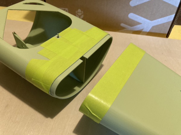
Clean up the printed parts carefully, mainly around the joins with sandpaper, craft knife, and file. Trim off the brims and check the joins for accuracy.
With Part E, the stern holes for the rudder and main sheet need to be clean and unobstructed with any print artefacts. It's a lot easier to discover and fix any issues before joining the hull parts.
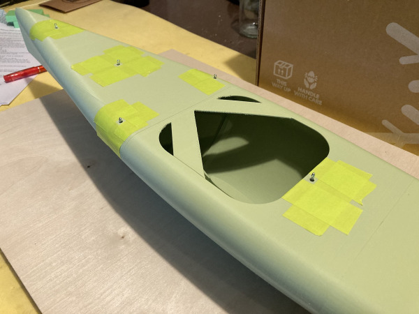
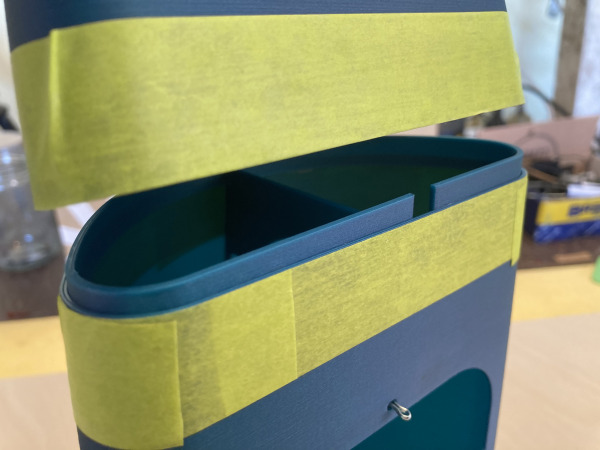
Masking Tape the hull joins on both sides of the joins so when you glue them together you don't get glue over-run at the joins.
4.2. Anchor Points
-
I - RG65 - Anchor Points x 5.stl
-
J - RG65 - Stay Washer x 5.stl
-
Super Glue (CA)
-
Masking Tape
-
Split Pins / Cotter Pins
For the Una Configuration there are only 2 central anchor points to attach while the Standard Configuration has 5 anchor points.
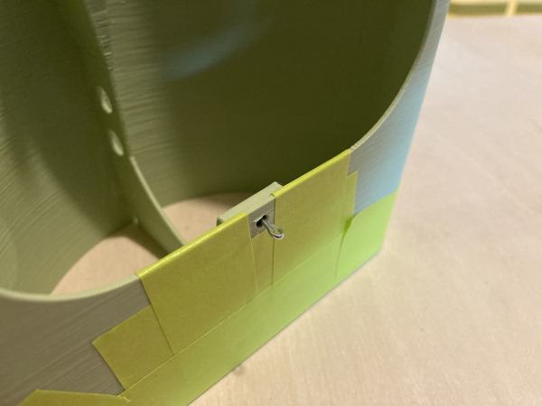
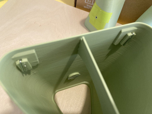
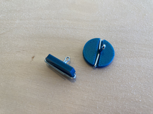
Build one sheet anchor by bending a split pin with pliers to form a T-shape. Super glue the t shaped pin into the anchor block. You may need to clip the ends of the split pin to make it fit in the slot.
Tape around the hole on the top side of the deck to stop finger marks then glue the anchor from inside the hatch with superglue. Make the loop of the metal pin front-facing.
4.3. Hull Assembly
-
Super Glue (CA)
Super glue the hull together starting from the back of the boat and work forwards. Use plenty of glue to ensure the joins are water tight.
To glue the stern and mid sections together you will first need to glue part F - RG65 - Mid-Stern Joiner.stl into the mid section first. This part is required because of the angle of the sides of the hull don't allow a workable print in place join so a reversed join needs to be glued in first.
Now that the boat is now one piece and while the tape is still on the hull, run a bead of superglue along each join, then quickly wipe away the excess with a clean rag. This will seep into the gap and weld the joins together.
Remove the tape straight away before the glue sets completely.
4.4. Hatch Opening
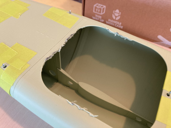
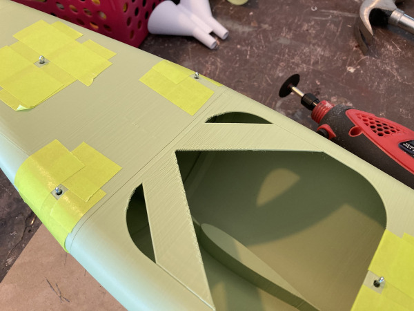
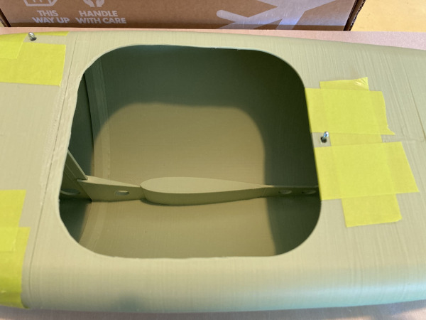
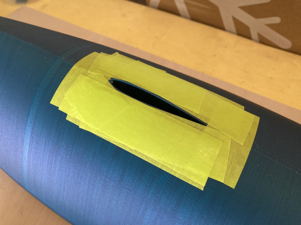
Use a dremel or a craft knife and cut off the print supports. Clean up the hull opening so it's clean and has no rough edges. Test fit the hatch plate to make sure it sits flat on the deck.
The standard rig hatch plate has the mast step locator while the Una rig hatch plate has no need for a mast step locator.
4.5. Sheet Exit Tube
-
E - RG65 - Stern.stl
-
Super Glue (CA)
-
Masking Tape
-
Brass Tube 1/8
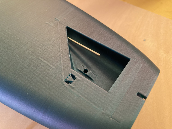
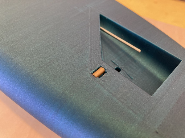
First break off the print in place support triangle covering the hole and clean up the edges with a craftknife and/or file.
Mark the brass tube length against the exit hole with a marker pen.
Cut the brass tube slightly oversized with a Dremel or Hacksaw then file the ends until there is a snug press fit. Glue with small drops of superglue in each seat in the PLA+.
4.6. Servo Bracket & Bracing
-
G - RG65 - Floor Brace.stl
-
O - RG65 - Servo Bracket.stl
-
O2 - RG65 - Bracket Grip Tab.stl
-
Super Glue (CA)
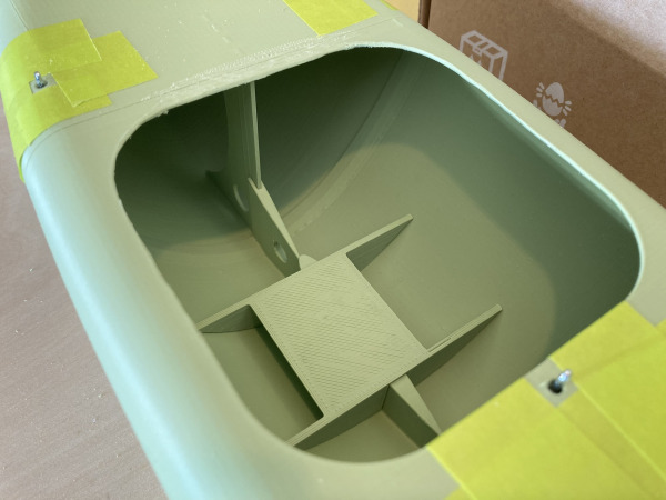
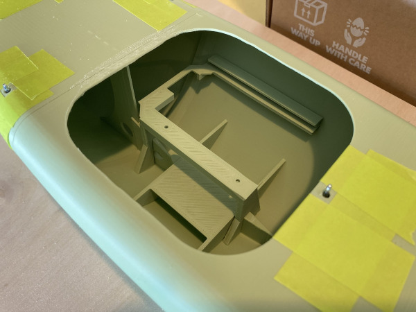
First test fit the floor brace. It's an important part of the boats structure and needs to fit properly. Trim carefully with your craft-knife so it's sits well on the keel trunk. Glue in place with plenty of CA glue. When the glue sets run a little more glue around the joins so that the gaps soak up more glue and the bond becomes more solid.
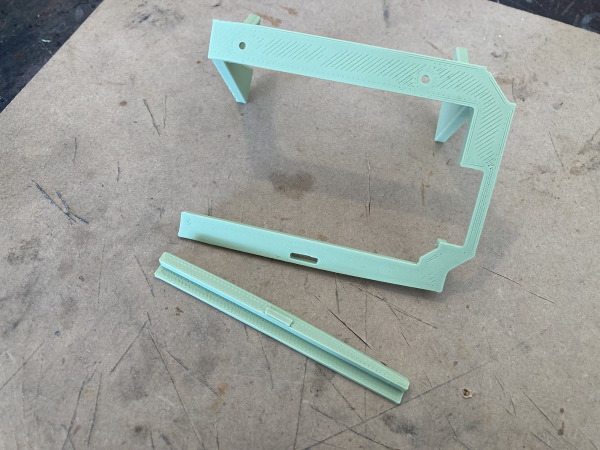
The servo tray bracket comes as two printed parts. Glue the tabbed piece to the bracket first, then install that component into the hull. It should sit against the hull and once the glue sets is a very strong piece of structure.
These parts do feel quite brittle and fragile when on their own but once they are all joined together they form a very strong but lightweight bracing system.
5. Electrics
The electrics are identical for both Una and Standard rig types. You use the same servo tray which is removable. You can easily re-use or swap electrics with another boat. You could build both styles of boat and have one servo tray between the two. Simply unscrew the sail arm and rudder horn. Then remove the 2 screws and the plate comes out as one piece.
5.1. Servo Tray & Binding Receiver
-
P - RG65 - Servo Tray.stl
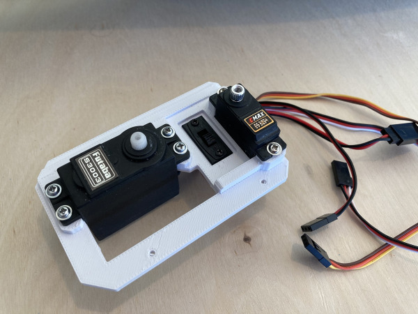
Screw in place the on/off switch.
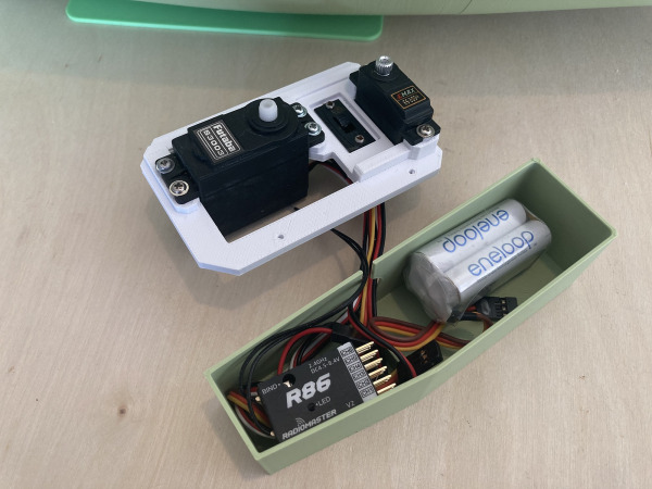
Screw servos onto the servo tray. Use just the screws the servos come with and no rubber feet or ferrules needed.
While the servos and wires are outside the boat is the best time to bind the transmitter to the receiver and program the input channels. This will be quite specific to the brand of gear you have.
To put the receiver in bind mode press the small button on the receiver and at the same time switch the on button and give the receiver power. A red light will then flash.
Search youtube and google for relevant information on how to bind and program your transmitter. I find on my RadioMaster Pocket that channel 1 is rudder and channel 3 is the sail arm by default. I plug the battery switch into channel 5 or 6.
The battery compartment fits a 4xAA square pack; although we recommend 4xAAA square pack as it's 50-70g lighter weight. Pack out the battery with some foam to keep it snug whilst sailing.
Note: there is a STEP file for the servo tray so you can adjust the 3d model to your specs if the servos you have are a different size. You can open a STEP file in a program like Fusion360 to re-create a new STL file.
5.2. Battery Box
-
N - RG65 - Battery Case.stl
-
N2 - RG65 - Battery Lid.stl
-
Super Glue (CA)
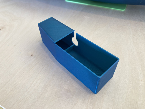
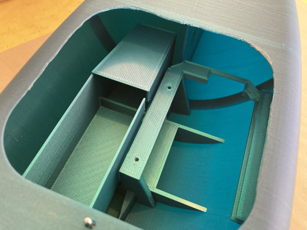
Glue the battery box lid to the battery box, When the lid dries glue the battery box into the hull. It is designed to keep the weight centralised about the keel. Use the photos as a placement guide.
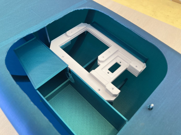
5.3. Servo Tray Installation
-
Small 3mm screws
Install the servo tray and route the wires into the battery box. Screw the servo tray into the hull with the two 3mm screws. No glue needed!
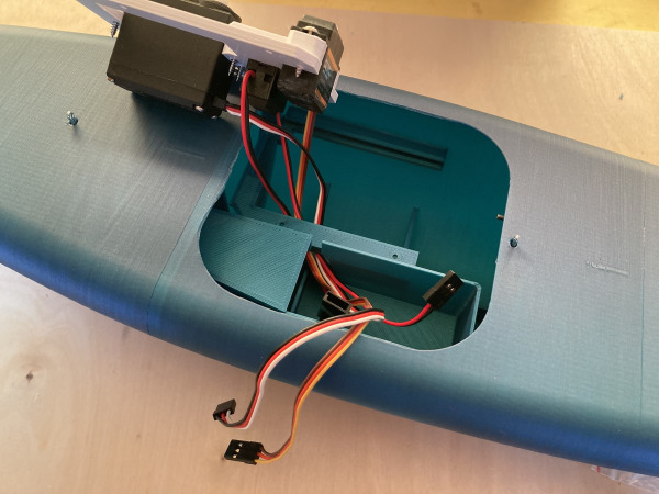
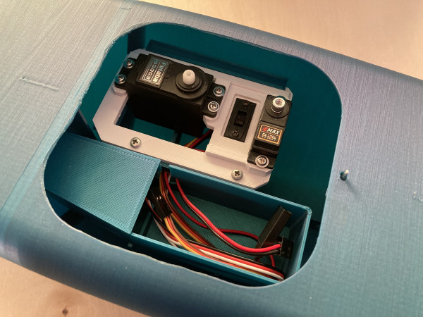
5.4. Sail Arm Installation
-
Q - RG65 - Sail Arm.stl
-
Super Glue (CA)
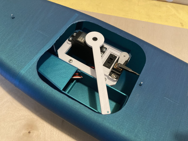
For the sail arm glue a round servo horn to the underside of the printed sail arm using superglue. It welds the two together and is very strong. Make sure to glue it centred. The top side needs to be accessible for the servo screw.
The servo should throw the arm 90 degrees giving the perfect amount of travel for the boom. When the arm is in the sail out position it should just be clear of the rudder servo mechanism by 3 or 4mm.
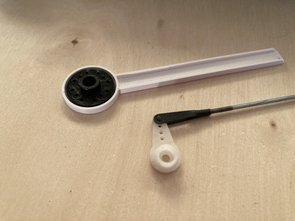
5.5. Hatch Plate
-
M - RG65 - Hatch Plate Standard.stl
-
M2 - RG65 - Hatch Plate Una.stl
-
Super Glue (CA)
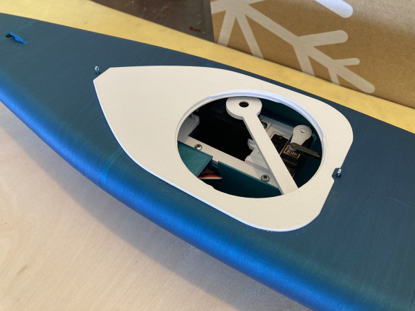
There are two different hatch plates. Una and Standard rig. They both have the same hatch opening and both use the same lid.
Test fit the hatch plate and ensure nothing is rubbing when the arm turns. Measure twice, glue once!
When happy apply plenty of super glue to the underside of the plate and glue it to the deck whilst applying moderate pressure for 20 seconds.
Note: the hatch lid has a small printed hole, which is the starting point for closing the hatch. Line up the two dots then twist clock-wise firmly to close.
5.6. Seal the Anchor Disks
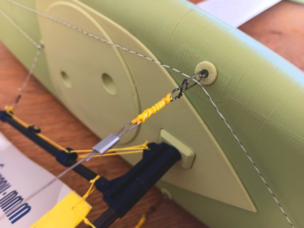
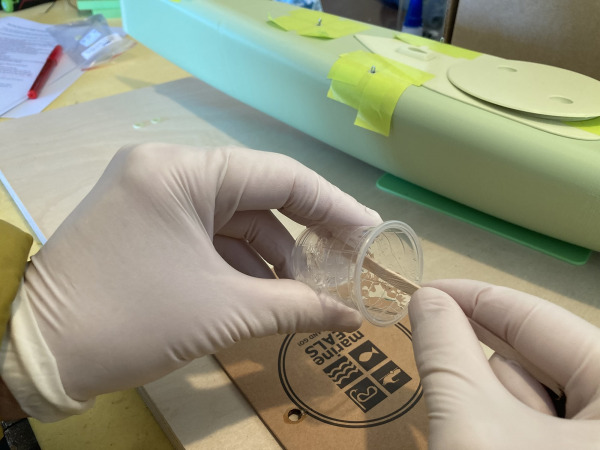
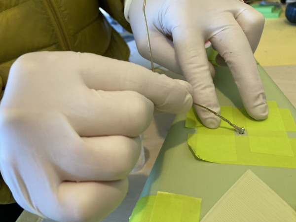
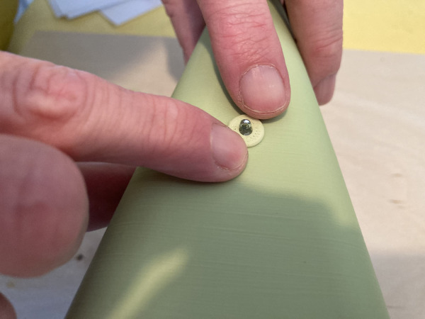
To seal the anchor disks we need to Epoxy fill the small gaps around the split pin and then place a printed washer over the top for a nice clean looking fitting.
For the Una boat there are only two of these anchors.
For the Standard config there are two anchors. The side stays washers are slightly different. They need to be bent to a rounded shape to match the hull curve. Do this by heating the printed washers on your 3D printer bed at 60C. When they are heated and softened bend the washers around something like a pen, a screwdriver or some object with a similar radius to the hull.
Once they fit nicely do the same and epoxy these in place and pop the washer on-top.
6. Rudder & Mainsheet Installation
6.1. Main Sheet Routing
-
Braid Line
-
Fishing Clip & Swivel
This is the same for both Una and Standard Sail Configurations. Later in the process we will rig up the rest of the lines to the respective sails.
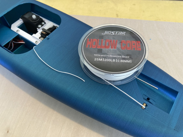
Direct from the spool thread your braid line through the stern hole in the boat. Let gravity do the work by standing the boat on it's bow and threading the braid carefully down through the hole. It may take a number of attempts, this is normal!
Once you see the braid inside the boat grab it with pliers or fingers and pull through some length.
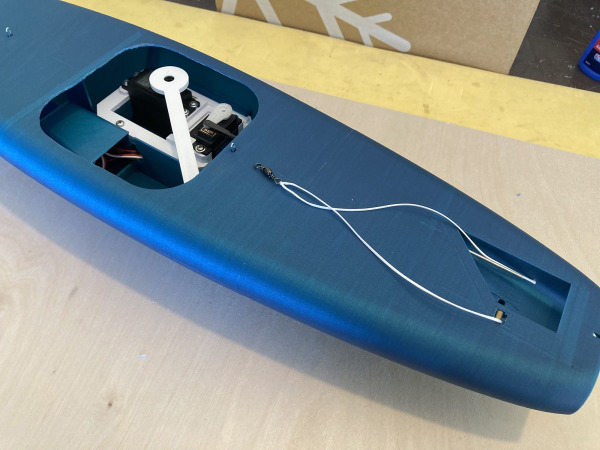
Tie the braid to the sail arm then CA glue the knot for a permanent fixture.
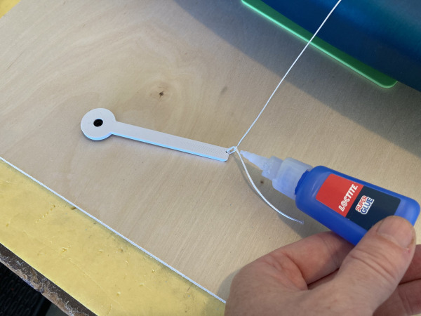
Now from out side the boat cut the braid to length then feed up through the brass exit tube and tie to a fishing swivel. When the arm is fully in-board the swivel should be 1cm away from the brass exit tube.
Once the above is CA glued you now have the main sail control line sorted and ready for a later stage in the project.
6.2. Rudder Build
-
Super Glue (CA)
-
Carbon Rod Round 3mm
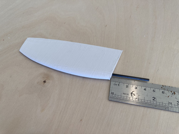
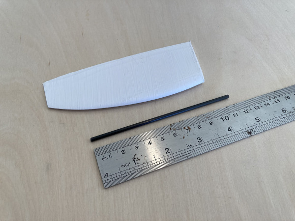
The rudder is very simple to put together. Simply glue in place a 3mm carbon rod - 112mm long. Test fit first. You may need to carefully drill out the hole so the carbon is not a struggle to insert.
I often add plenty of CA glue to the carbon. Pop the carbon into the hole and quickly hammer in place before the glue takes hold. Then spin the carbon briefly to spread the glue inside. Now leave to set.
6.3. Rudder Control Rod
-
T - RG65 - Tiller Arm.stl
-
Rudder Control Rod & Clevis
-
Tiller Arm Bolt
-
DB608 Kwik Grip - Rudder Arm Connector
Note the measurements needed for the push rod.
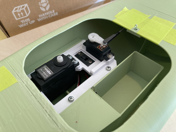
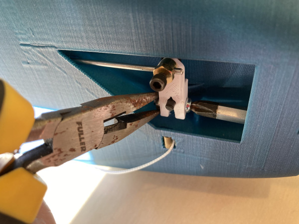
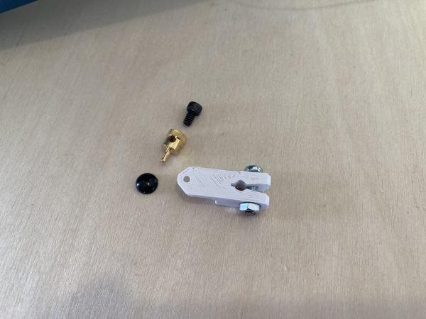
The threaded part will end up attached to the servo control arm inside the boat. Attach the control horn to the rudder servo arm. I usually cut down a four arm attachment so it has just one remaining. Most servos seem to come with a four arm servo horn.
For the rudder attach the push rod to the printed tiller arm either with a z-bend; which you can make with 2 pairs of pliers. Or you can use a bought part like the Dubro Kwik Link which is more accurate and tidy.
6.4. Rudder Setup & Centering
Ideally you want the rudder as centred as possible with neutral trim on the transmitter. If using a z-bend at the tiller end turn the clevis on the thread to get the best push rod length then screw the servo arm to the servo.
Now fine tune the centering with transmitter trim controls.
To have a really smooth sailing experience I program lots of expo into the rudder so that any control inputs on the rudder are very subtle to begin with and ramp up as the controls move toward their end point. You don't need a lot of rudder movement sailing upwind with the RS-RG65, she is very balanced and will sail herself most of the time.
7. Keel Build
7.1. Keel Halves Assembly
-
R - RG65 - Keel Bottom.stl
-
S - RG65 - Keel Top.stl
-
Super Glue (CA)
-
Masking Tape
-
Carbon Rod Round 3mm
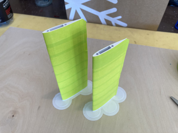
Using masking tape cover the keel completely with tape to stop glues and hand marks while you build. Make sure you leave the end clear of tape so it can glue into the bulb slot.
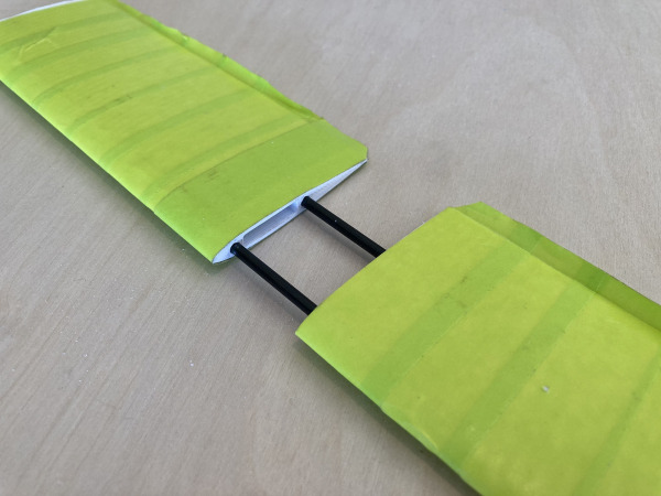
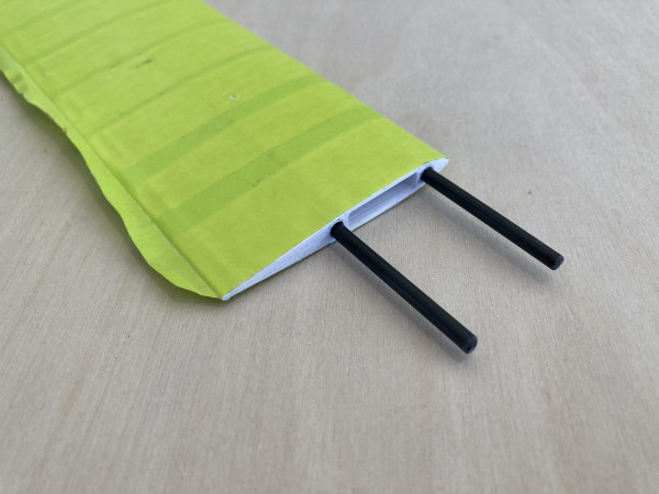
Cut 2 lengths of 3mm Carbon rod to 75mm in length. Clean up the ends up with sandpaper. Super glue the keel together with the 2 rods.
7.2. Join Bulb to Keel
-
Bulb A - RG65 - Bulb Main 550.stl
-
Bulb C-D - RG65 - Bulb Main 475-508g.stl
-
Super Glue (CA)
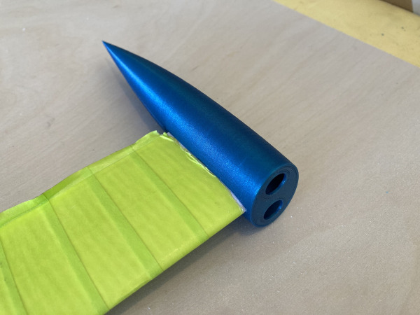
Prepare the keel to fit neatly into the bulb trench. Small trims the keel edge. It should be a tight fit ideally. Then CA superglue in place.
7.3. Carbon Reinforcement
-
Carbon Square Rod 4mm
-
Epoxy Resin
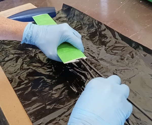
Prepare an area for gluing the carbon square 4mm rods into the keel. An old scrap of cardboard box is an ideal way to do this. This is going to get messy.
Wearing gloves mix some epoxy resin. You need to mix enough to completely coat all 4 rods on all sides.
Do this with your hands whilst wearing the gloves. Slide the 4 rods into the keel trench so they go all the way to the bottom; right through to the base of the bulb. You may need to tap them in place with a hammer.
I find it a useful to switch to a fresh set of gloves part way through so you don’t cover your tools in glue. Leave the keel sitting upright whilst drying to prevent unwanted curvature.
7.4. Bulb Filling
-
Epoxy Resin
-
Methylated Spirits / Denatured Alcohol
-
Lead Shot
Place keel upright with bulb nose supported.
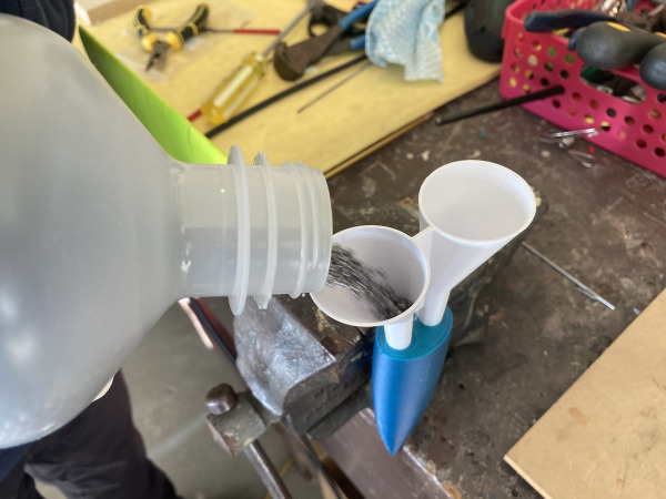
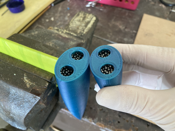
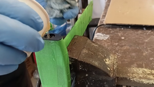
Fill bulb with lead shot leaving 1cm gap. Use the printed funnel to assist in the pouring of the both the lead and the resin.
Prep the area for resin drips, cardboard underneath and a rag to mop up an drips or excess resin. A change of gloves part way through can be a good idea.
Mix 50ml resin thoroughly, then add 15ml mineral turpentine and mix again. Now slowly pour resin in via the funnel allowing it to soak through lead shot. It's a slow process that requires some patience.
Tap bulb to release air bubbles. Top up with lead and resin so that it goes all the way to top of each part.
Leave these to sit for around 12 hours or until completely set.
7.5. Final Keel Steps
-
Super Glue (CA)
-
Masking Tape
-
Epoxy Resin
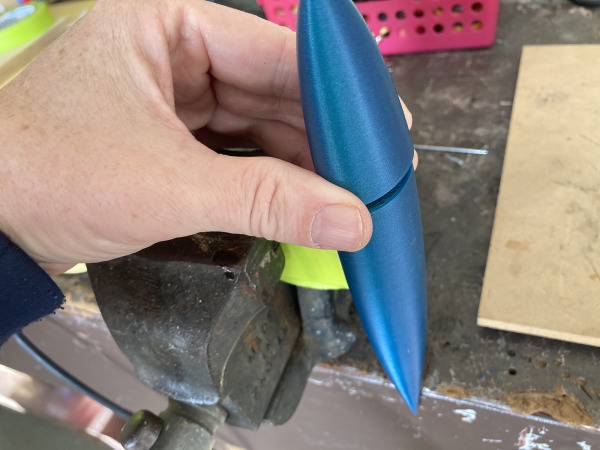
Once the resin and lead has set, give the bulb a light sand where the two halves will meet and be joined. You want to remove any resin that has a set on the flat surfaces. You want to glue plastic to plastic for a strong bond.
Add superglue and join the two halves together. Practice this a few times first to get your technique and fit/feel just right.
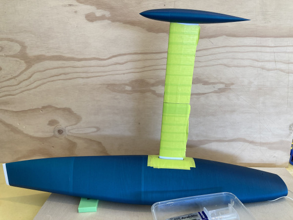
To glue the completed keel component into the hull mix a small amount of epoxy and line the cavity in the hull. Insert the keel, give it a good wiggle and leave the boat upside-down for a 12-24hrs wait.
8. Standard Rig (Main & Jib)
8.1. Mast Step
-
H - RG65 - Mast Step.stl
-
Super Glue (CA)
Test fit the mast step, making sure it's facing the correct way. It should fit nice and snug.
Super glue the mast step in place with plenty of SuperGlue.
8.2. Cut Mast & Boom Sections
-
Carbon Tube 6mm
-
Carbon Tube 5mm
Before cutting your carbon tubes carefully study the lengths required. Both boat types come with A & B rigs. The B rigs are smaller sets for higher winds. The measurements are in mm.
The lengths can be found in the Sail Plans tab. Each sail has two images. One sail plan and another spar plan which shows the lengths the carbon need to be cut to. The numbers shown are the lengths of the carbon, not the total of carbon and join. For instance the Una A rig boom length says 285. That is how long you need to cut the carbon boom for that rig.
The mast is made from 6mm carbon tube. The booms are 5mm carbon tube. This helps the booms bend as much as the mast.
A Dremel with a cutting disk is the easiest way to cut the tubes but a hacksaw would also do the job. Tidy up the cuts with some sand paper.
Note: Wear gloves if possible. It's healthier and stops itchy hands. Wear a mask too when cutting. The particles are not good for the lungs!
8.3. Mast Fittings & Spreaders
-
Rig B - RG65 - Mast Crane.stl
-
Rig C - RG65 - Spreader Set.stl
-
Rig D - RG65 - Boom Attachments x 7.stl
-
Super Glue (CA)
-
Carbon Rod Round 3mm
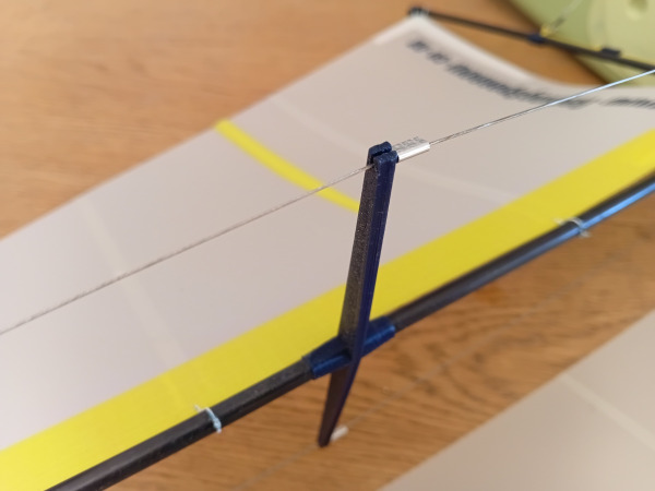
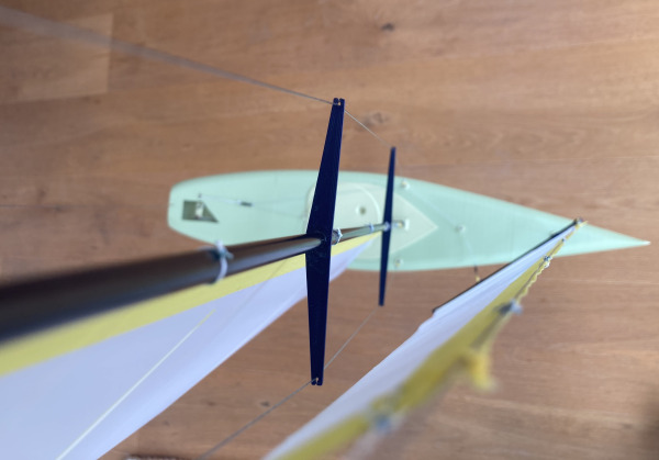
The standard rig mast has two spreaders, the positions these need to be attached are in the Sail Plans tab. The larger bottom spreader is made from two pieces and glued together for strength.
The top spreader is one piece and the rake actually faces forward. This seems counter intuitive but the sail shape is much better if the mast stays straight. The inverted top spreader helps to counter the backstay which tries to bend the mast when under tension.
The topper simply glues in place. It has an internal 3mm carbon rod to add strength to the PLA+.
Ensure the Topper and Spreaders are perfectly aligned to right-angles to each others axis.
8.4. Gooseneck Installation
-
Rig A - RG65 - Gooseneck Set.stl
-
Super Glue (CA)
The goose neck is glued to the mast. It's does not glue to the mast step. The mast is kept in position via the tension from the wire stays.
The only parts that require gluing are the main mast tubes. The smaller brace is supposed to free pivot on the lugs. Sand the carbon lightly before gluing to rough up the surface. This helps the CA bond much better.
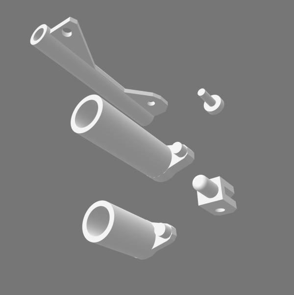
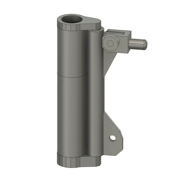
Start by test fitting all the part then slide the top part of the main trunk up and out of the way. Glue (CA SuperGlue) the bottom piece in place. Once the glue sets glue the top piece in place by sliding it down and at the same time pop the brace in the lugs to secure.
The mainsail boom has a small part that glues in the end and a printed pin joins the swivel join together. See the 3d render image showing you the parts.
8.5. Boom Attachments
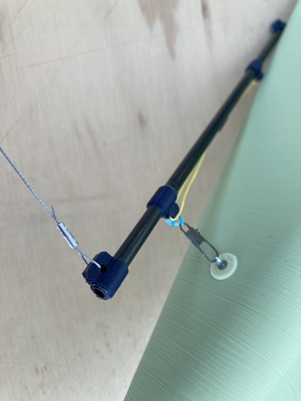
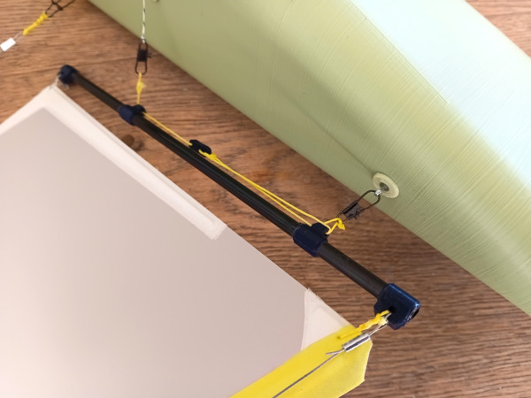
The printed boom attachments glue in place with CA glue. Lightly sand the carbon first.
Get the measurements from the Sail Plans tab. Ensure they are in the correct spot by test fitting all of them first without glue.
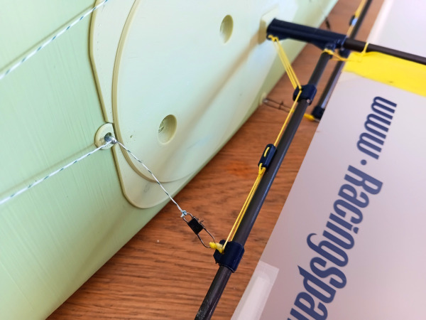
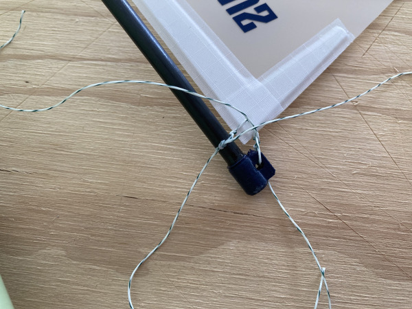
The mid attachment point uses a double loop of braid with a knot as a simple way to clip a fishing clip to the attachment. It's strong, simple and also twists allowing some flexibility in the connection.
8.6. Rigging Wires
-
Stay Wire
-
Stay Crimps
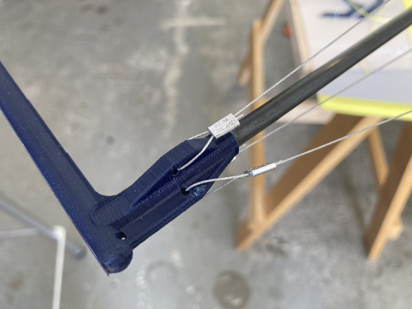
Cut lengths of wire for the forestay, side stays and backstay. Make sure to add extra to allow for a loop at each end.
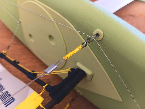
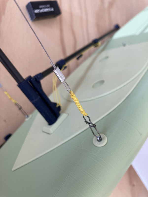
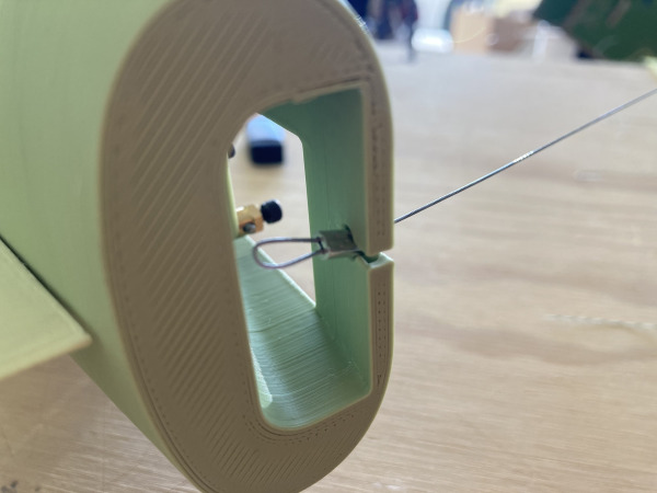
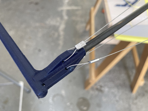
To crimp two wires together thread through the crimp then through the attachment hole on the mast fitting. Then back through the crimp to form a loop.
Attach to the top of the mast first including the backstay on the end of the mast topper. Fix all 4 stays using wire crimps and the fishing lure wire. Use pliers initially to crimp the the small aluminium tubes. Then use a hammer and squash them a bit more with a few hits. Trim the trailing edges. I like to leave the same amount of around 3mm tail. This way if one slips when sailing I can visually see the slippage as they all should match. They only slip if the crimp is not squashed enough to clamp the two pieces of wire together.
8.7. Tension Stays
-
Super Glue (CA)
-
Braid Line
Position the Mast
Use a temporary forestay and backstay to hold the mast upright while fitting and tensioning the side stays. You can do this whilst laying the boat on its' side or propped up against a wall.
Prepare the Side Stays
The side stays should be firm when tensioned by hand, without the spreaders attached.
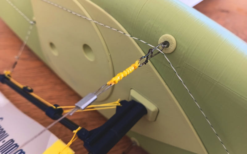
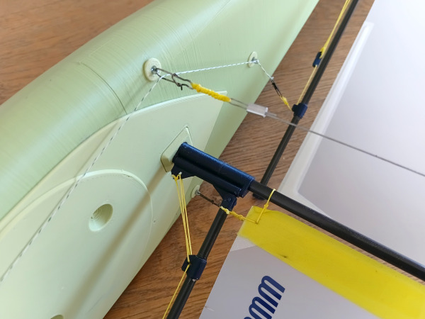
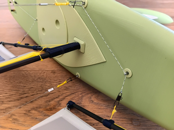
Create a loop at the bottom of each side stay, leaving approximately 2 cm between the stay loop and the attachment point on the hull. This gap allows you to tension and secure the stays using several passes of braided line.
Tie the braid to the side stay loop, then pass it down through the fishing clip on the hull anchor and back up again. Repeat this three times to create a multi-strand tensioning system.
Prepare both side stays in this way before applying the final tension.
Tension and Secure the Side Stays
With the spreaders still disconnected, tension both side stays together. The friction between the strands of braid should hold the tension long enough for you to secure each side.
Check that the mast is as vertical as possible by eye, adjusting the tension on each side as required.
To secure the braid, wrap the loose end tightly around the tensioned strands, working your way down the full length of the 2 cm gap. Tie it off securely at the bottom.
Repeat this process on both side stays. Once you are satisfied with the mast alignment and tension, apply super glue to the braided bindings to create a solid, permanent fitting.
Once the glue has set stretch the side stays onto the spreaders and the tension will increase to a nice guitar string like firmness.
Attach the Backstay
Attach and tension the backstay, allowing a slight backward rake in the mast.
The backstay uses a simple loop at its attachment point, held securely in place by the tension of the rig.
Attach and Tension the Forestay
The forestay is tensioned last, once the side stays are secured, the spreaders are fitted and the backstay is attached.
The cantilevered jib boom should provide enough tension to introduce a very slight bend in the mast.
Once the jib sail is tied to the end of the boom, the boom should tension the trailing edge of the jib while also maintaining a firm, straight forestay.
The finished rig should have evenly tensioned side stays, a slight backward mast rake and a straight, well-supported leading edge on the jib sail.
9. Una Rig (Single Sail)
9.1. Cut Mast & Boom Sections
As with the standard rig, carefully check the carbon tube lengths before cutting. The Una rig also comes with A and B rig options, with the smaller B rig designed for stronger winds.
Refer to the Sail Plans tab for the correct mast and boom lengths. Remember, all measurements are in millimetres and refer to the carbon tube only, excluding any joining fittings.
Use 6mm carbon tube for the mast and 5mm for the boom. Cut with a Dremel or hacksaw and tidy the ends with sandpaper.
Safety: Wear gloves and a dust mask when cutting carbon fibre to avoid skin irritation and inhaling dust.
9.2. Mast Disk Installation
-
Rig I - RG65 - Una Mast Disk.stl
-
Super Glue (CA)
Slide the joiner up the mast and out of the way in preparation for the next part.
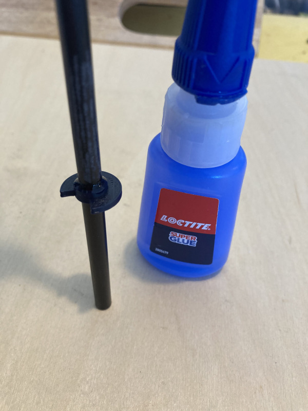
Insert the mast into hull, position the disk so the mast spins freely but cannot lift out. Once happy with the disk placement gently remove the mast from the hull and glue the disk by running superglue around the top and bottom. The glue will seep into the gaps and bond it.
Wipe away any excess glue and let the glue dry.
9.3. Spar Joiner & Boom
-
Rig H - RG65 - Una Rig Spar Joiner.stl
-
Super Glue (CA)
-
Carbon Tube 5mm
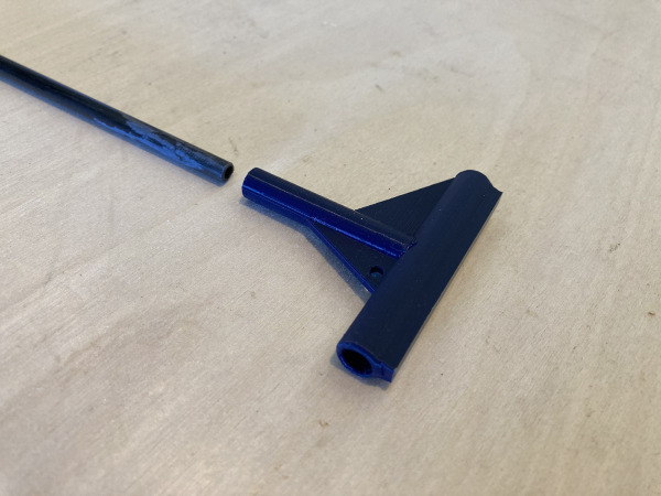
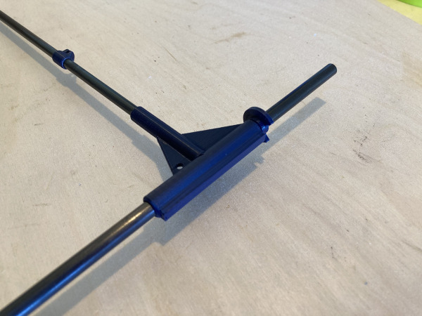
Add plenty of glue to where the joiner will sit and quickly slide the joiner in place before the superglue takes hold. You only get one chance so practice first and prep well. Measure twice, glue once!
Now glue the joiner against disk with the disc notch facing forward.
Lightly sand the boom end and glue the carbon boom into the joiner.
9.4. Mast Topper
-
Rig G - RG65 - Crane Una Rig.stl
-
Carbon Rod Round 3mm
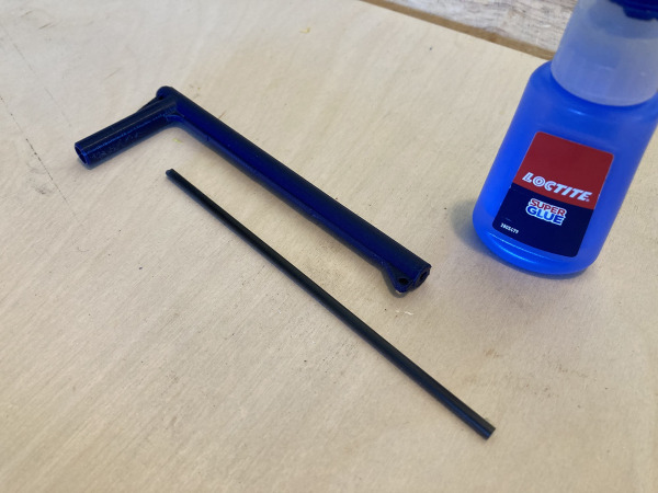
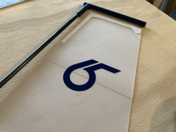
Test fit the 3mm carbon tube inside the topper. When happy apply plenty of CA glue to the carbon rod and slide into the topper. You may need to tap it in with a hammer. Trim the end with sandpaper so it's tidy and no carbon is sticking out.
Now test fit the topper on the top of the mast. Sand the 6mm carbon mast tube so the topper will adhere better with the CA glue.
Make sure when you glue the topper in place it lines up perfectly with the boom. Now apply CA glue to the carbon and slide the topper in place. Wipe away excess glue with a rag.
9.5. Boom Attachments
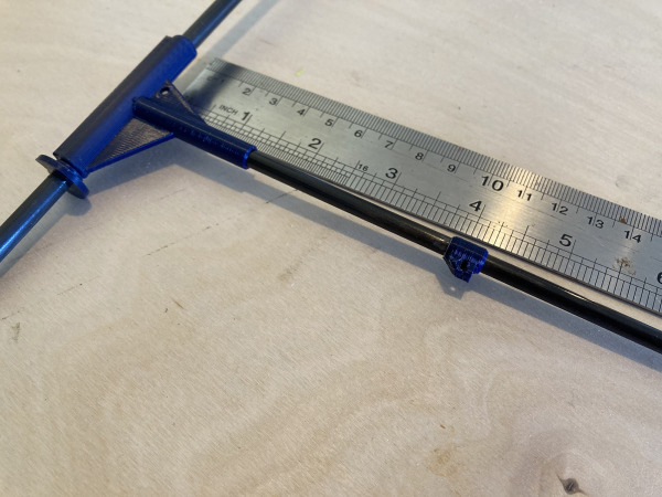
Take the measurement for the mid attachment point from the plans and lightly sand the carbon where the part will glue on. The mid attachment point is on the underside of the boom. Practice first to make sure you can align the part nice and straight. Now CA glue in place.
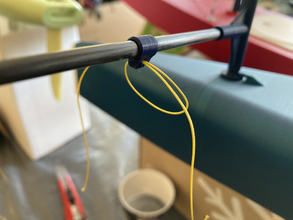
The mid attachment point uses a double loop of braid with a knot as a simple way to clip a fishing clip to the attachment. It's strong, simple and also twists allowing some flexibility in the connection.
For the end attachment point do the same but this time the attachment is on the top side of the boom.
Once this is done the Una spars are complete.
10. Standard Sails
10.1. Workspace Setup
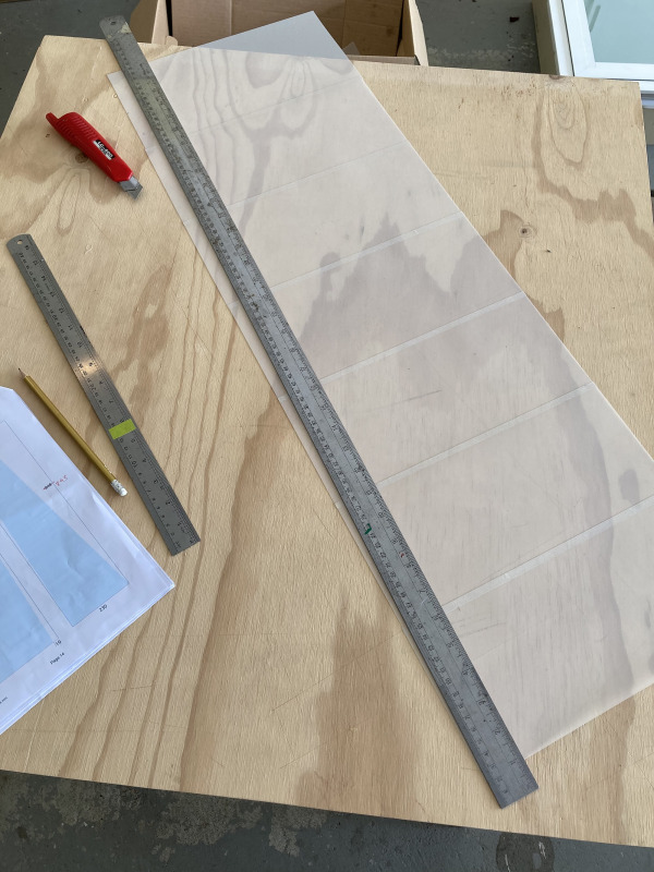
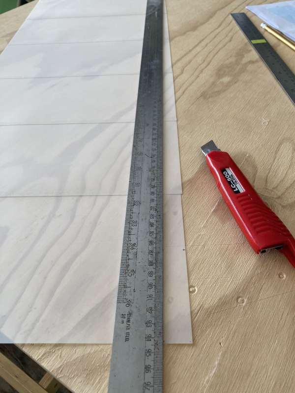
Use a flat, cuttable surface such as scrap vinyl, plywood or cardboard.
10.2. Main Sail Cutting
-
Sail Material
The sail is ideally made from one piece of material. No seams are needed unless your material you are using comes in smaller pieces like A4 architectural drafting film. You can use many things for sail material. Drafting film, reflective grow mylar, ripstop nylon, spinnaker sail offcuts, floral mylar. If you need to; first join panels of material to form one large rectangle as per the sail plans.
Cut the sail rectangle from your one piece material using the plan dimensions.
Measure, mark then cut the mast and boom offsets according to the sail plans.
Measure, mark then cut the square top measurement down to the bottom corner to complete the final outer shape of the sail.
10.3. Jib Cutting
-
Sail Material
For the Jib follow the same process much like the main sail but use the jib dimensions. Use the exact measurements as stated and the sails will hold the correct tension as needed. They will seem slightly too short in the leech. The booms do end up bending up a little bit and creating a tight sail leech.
10.4. Corners & Battens
-
Spinnaker Repair Tape
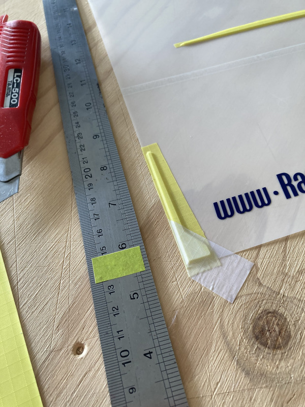
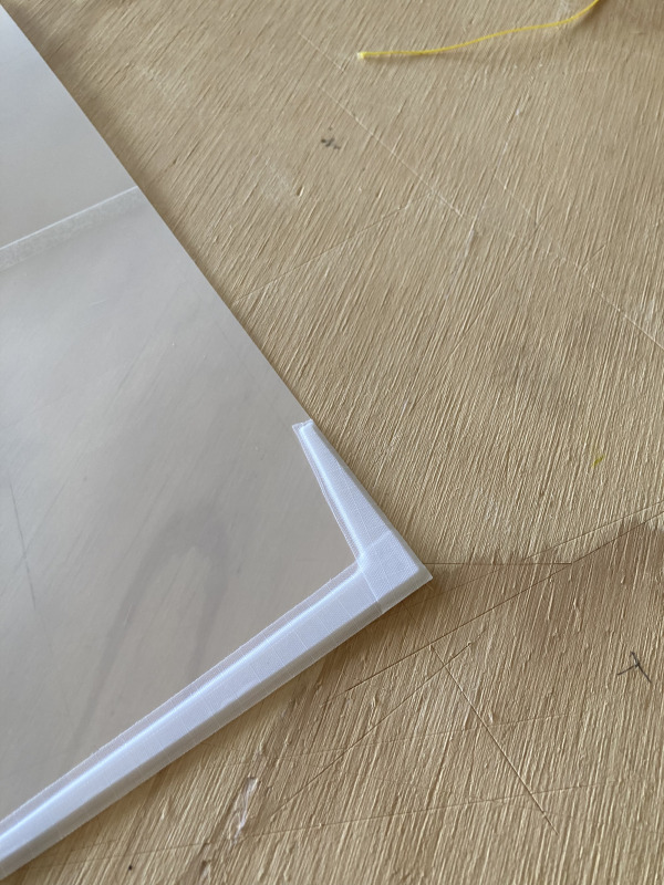
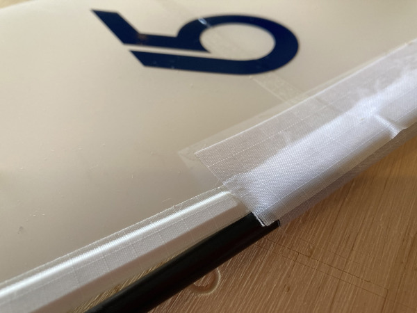
Tape the 3D printed corners in place using spinnaker tape. The tape should go well past the sail edges. Next you will trim these edges off with a craftknife.
Install the sail battens using tape strips. Find placement measurements on the sail plans.
Make sure to use the correct size battens from the STL fileset. Each set have some slight variations specific to each sail.
10.5. Leading Edge Tape
Apply sail tape to both sides of the leading edge stretching the sail while taping.
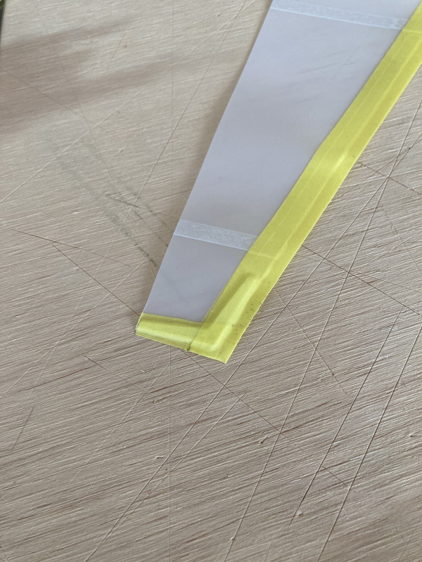
For this step it really helps if someone helps you to stretch the sail as you apply the tape. This will reduce any unwanted wrinkles.
Trim the tape to leave a 5mm double thickness leading edge and flush edges.
At the top of the sail cut a notch in the tape down to the second square batten. That part gets in the way of the mast and disturbs the sail shape.
10.6. Lacing & Attachment
-
Braid Line
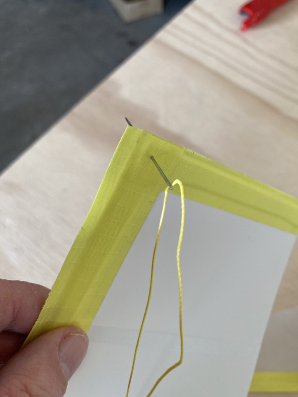
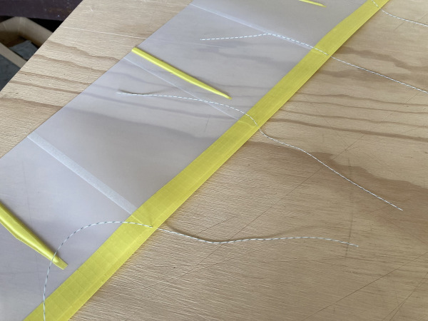
Starting at the top of the sail stitch the sail with a needle loaded with braid line. Instead of threading each loop and attachment point one at a time, it’s much easier to do this with one continuous length of braid meaning you only need to thread the needle with braid once.
Start at the top through the eyelet then every 100mm pop the needle through the leading edge sail tape. Work your way down the sail. Once down to the sail tack move across to the clew. As you do this you will need to keep threading more braid through the existing holes you have made.
Now that you’ve got thread running through all holes you can remove the needle from the thread and starting at the top cut the braid into 200mm lengths.
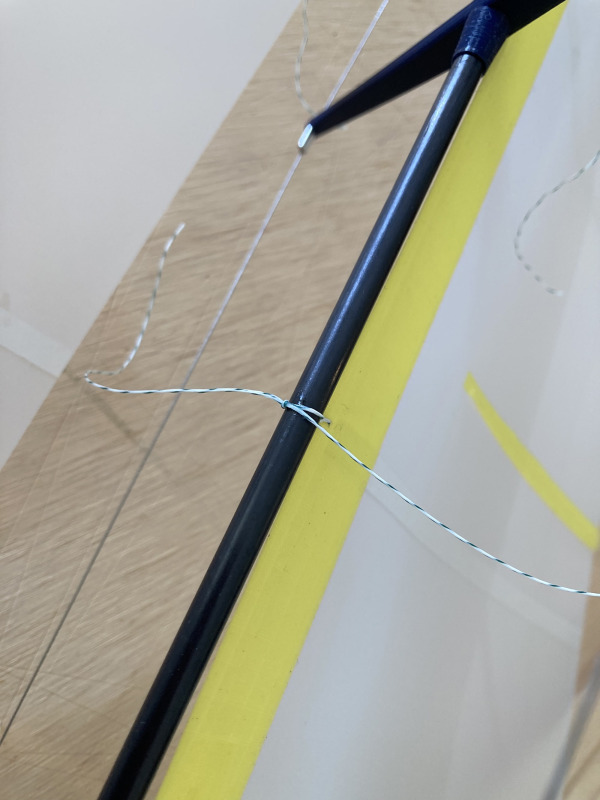
The clew will need a longer 300mm piece of rope loop. Now tie each loop with a simple reef knot attaching a small loop to the sail with 2 x 100mm tails.
Again starting at the top of the sail, tie the top line to the mast topper making it snug and as close to hole as you can. Then working down the mast tie each loop around the mast and loosely tie each attachment point. You don’t want them to be tight against the mast. You want them slightly loose so they can freely move around the mast and the sail will naturally form the correct shape governed by the sail battens.
When you get down to the tack you want to tie this so the front luff of the sail holds some tension.
For the clew it will attach in two places. The first attachment is a snug fit to the boom. The second will be the adjustable outhaul covered in the next step.
After this step superglue all the knots on the back of the mast with a small dot of superglue. This will make the knots permanent and is a great trick to reduce breakages whilst sailing. Once the glue has set trim all knot ends close to the knot with a sharp craft knife.
When this step is complete you should notice both the mast and boom have slight bends in them. The bend is great as it keep the sail tight and in the correct shape.
11. Una Sail
11.1. Sail Cutting
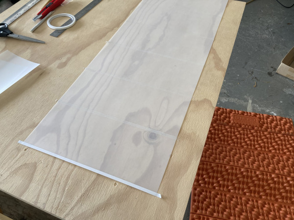
Ideally, make the sail from one piece of material. Suitable materials include drafting film, reflective grow Mylar, ripstop nylon, spinnaker offcuts or floral Mylar. If using smaller sheets, join them first to form one large rectangle.
Using the sail plan dimensions which are in the "Sail Plans Tab", cut the rectangle, then measure, mark and cut the mast and boom offsets.
Finally, cut from the square top to the bottom corner to complete the sail shape.
11.2. Attachment Points
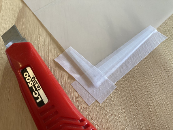
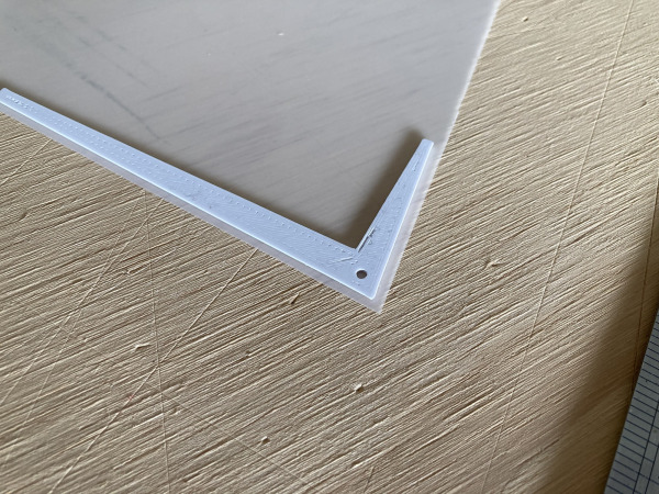
Using spinnaker repair tape, fix the corners in place. Each corner piece has printed 2mm holes which act as eyelets to give the corners strength.
Note: for the Una the top of the sail attaches in two places. At each end of the topper. The rig is all fixed and the topper rotates with the mast. This helps the sail have a nice straight trailing edge and provides excellent power.
11.3. Attach Battens
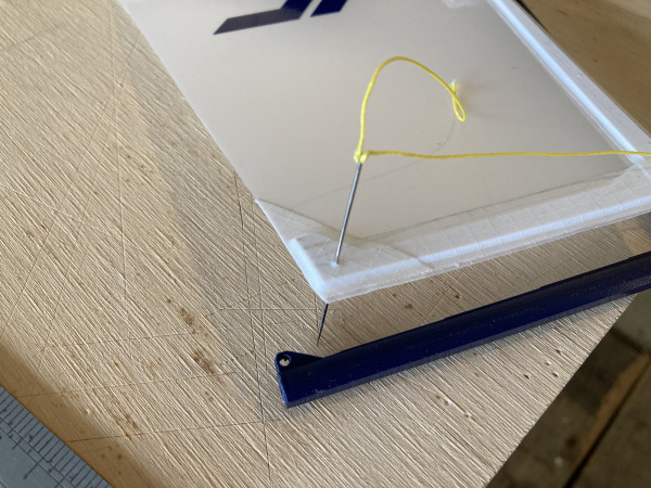
Place the battens in the places shown on the sail plans. It just needs to be similar or close to what is shown. It's not critical. Evenly space the gaps between more for visual appeal. The main thing is to have battens on the trailing edge. You can choose to not use all the battens. Tape 1 set of battens to 1 side of the sail. But add tape to both sides to ensure tape tension doesn't warp the sails as they heat and cool. Overlap the tape so the batten is sitting inside a little tape pocket.
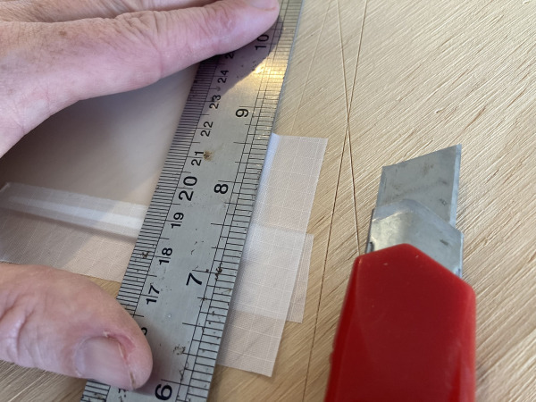
Trim all the edges of the tape that should be overlapping with a ruler and craft knife.
11.4. Attachment to Mast
For the Una rig you can attach the sail to the mast in a few different ways. Because there are no spreaders you can attach the sail with a luff pocket that slides down the mast. I use soft ripstop nylon for this style of attachment.
The other method of attachment is the same used for the standard sails. Check out that section which shows how it's done. I prefer that method as it seems to allow the sail to move on the mast more freely and creates better sail shape.
The sail should be tensioned up when attaching to the boom and mast so that the carbon spars have some bend. The sail should be quite firm and not sag. You are trying to emulate a solid wing shape like an aeroplane wing.
12. Main Sheet & Radio Setup
12.1. Sheet Routing
This section explains how to rig the braid control lines from the fishing swivel previously attached to the sail arm.
Mainsail Control Line – Both Rigs
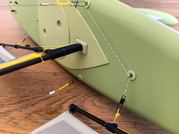
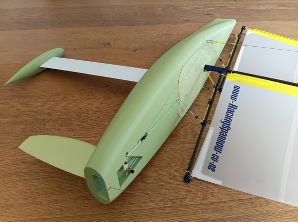
The mainsail uses a simple 1:1 control line. Run a single braid line from the fishing swivel, through the deck anchor point and onto the boom. Attach a fishing clip to the end of the line so the sail can be easily installed or removed.
No adjuster is needed for the mainsail, as its position can be fine-tuned using the transmitter settings.
To set the line length, move the sail arm to its fully pulled-in position, then tie the line as tight as possible. This should naturally position the boom close to the correct upwind sailing angle.
This setup is identical for both the standard and Una rigs.
Jib Control Line – Standard Rig
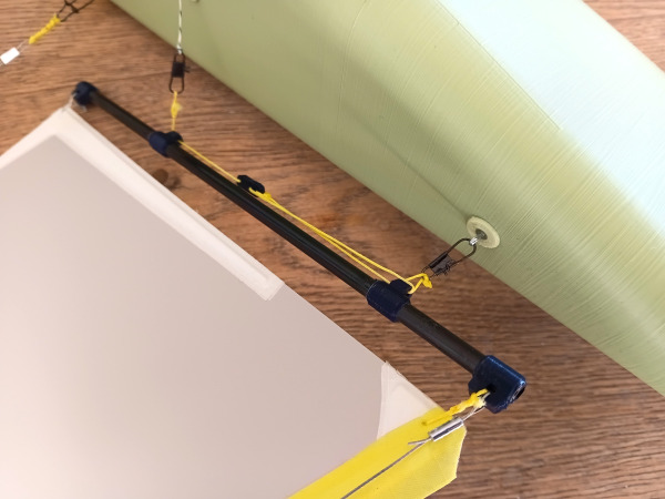
The jib requires a slightly different setup. Attach a second braid line to the fishing swivel, then run it through the sidestay clip, through the foredeck anchor point and finally onto a fishing clip.
With the sail arm fully pulled in, the fishing clip should sit just a few millimetres from the foredeck anchor point.
On the jib boom, install a printed bowsie adjuster. This allows you to adjust the jib position while sailing.
The slot between the jib and mainsail is an important part of sail tuning. Adjusting this gap helps control airflow between the sails and maximise sailing performance. Refer to the diagram for details on rigging the bowsie adjuster.
12.2. Boom Angle - Standard/Una & Jib Trim
Jib Sail Trim
When sailing upwind, a good starting point is to set the end of the jib boom roughly in line with the sidestays.
As you gain experience, try adjusting the jib closer to the centreline and see how the boat performs. One of the most common mistakes is setting the jib slot too narrow, which restricts airflow between the jib and mainsail. Keep the slot open enough for air to flow freely between the sails.
Mainsail Trim – Standard Rig
When sailing upwind, the mainsail boom should sit just off the centreline of the boat.
Rather than focusing on the boom position, pay attention to the trailing edge of the mainsail. Ideally, the trailing edge should be almost parallel to the boat's centreline.
Mainsail Trim – Una Rig
The Una rig has just one sail, so there is no jib to help direct airflow around the mainsail. This requires a slightly different setup.
When sailing upwind, position the end of the boom roughly in line with the rear corner of the hull. The sail should be set further out than on the standard rig, rather than pulled close to the centreline.
12.3. Radio Fine Tuning
Fine tune the sail trim via the transmitter trim buttons. You should only need a little bit of trim ideally.
Another excellent improvement to the handling of your boat is to add exponential to the rudder for fine control and reduced drag. Adding expo means the rudder makes more subtle movements. The RS-RG65 is very well balanced by design and does not need large rudder corrections when sailing in straight lines.
Remember every time the rudder is corrected it acts as a break and slows you down. Minimising rudder movement is key to sailing faster!
13. Ready to Sail
The boat is now ready to sail.
On the first sail, run the boat for about 30 seconds, return to shore, and inspect inside. You may need to add a little superglue to any joins or gaps you missed if you spy a leak.
When sailing, take a sponge, spare braid, and superglue. Be gentle on your first outing!
When built correctly, the boat remains very dry inside. The internal layout also lifts the electrics above any water, keeping the battery and receiver protected in their own compartment if water did get inside.
Well done and good luck sailing!
Printing Guide
The Racing Sparrow 3D boats are designed to be printed from PLA+. One roll of filament should be enough to print the hull parts, keel, bulb, rudder, and rig parts.
The 3D model has been designed so that no part is too large, making it easily printable on most home 3D printers.
Minimum printer bed size: 150 × 150 × 180 mm (XYZ)
Simply load the STL files into your slicer software and start printing. All parts are pre-oriented correctly, so you should not need to rotate them.
The following settings were used on a Creality K1 Max printer:
- Filament: eSUN PLA+
- Nozzle: 0.4 mm
- Wall count: 2
- Top layers: 4
- Bottom layers: 4
- Bed adhesion: Brim inside and outside for thin hull skins
- Mouse ears: Use keel and rudder blades
- Nozzle temperature: 200°C
- Bed temperature: 60°C
- Enclosure temperature: 34°C
- Print speed: 300 mm/s
Carbon Fibre
Before gluing any carbon fibre, it's best to sand off the glossy outer coating of the spar. These coatings are thin layers added by manufacturers. Removing the coating will create a much better bond between the carbon fibre and PLA+.
It's easiest to sand these with a Dremel, although this can also be done by hand with sandpaper. Wear gloves to avoid irritation from carbon fibre particles.
Carbon fibre bonds well with both CA and epoxy glues.
Rig Notes
Note that the top spreader is intentionally inverted. This helps keep the mast straight when the backstay is tensioned.
The boom dimensions may be shorter than the sail foot, as you want some loose curvature in the foot of the sail.
Tie the sails to the attachment points for optimal sail tuning. Set and forget!
Electrics
The batteries used for this model are a 4-cell AAA Eneloop pack with a JR plug, providing a 4.8V power supply.
The prototype uses inexpensive servos: a standard Futaba S3003 for the sail arm and an EMAX ES3054 20g mini servo. Both are affordable options.
The receiver and transmitter can be any suitable radio system, although I prefer RadioMaster products. They've proven reliable over the years and offer excellent value for money.
Sail Materials
You can use several different materials for making sails. I use foil Mylar for my prototype boats, as it's very inexpensive.
For my final models, I prefer architectural drafting film. Ripstop nylon is another option, with sewn edges.
For sail tape, I use spinnaker repair tape.